Answer
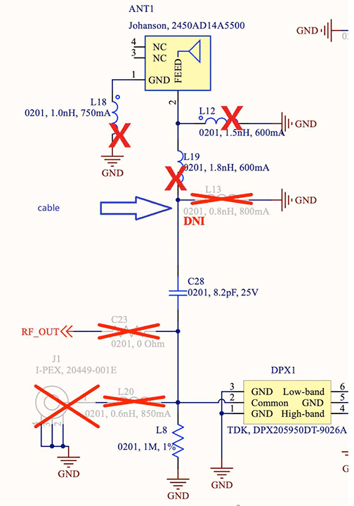
The below picture shows part of the schematics and indicates where to connect a coax-cable and which components to remove for the measurement. The cable need to be solder at C28 and ground as close as possible.

The below picture shows part of the schematics and indicates where to connect a coax-cable and which components to remove for the measurement. The cable need to be solder at C28 and ground as close as possible.
