Module, RM1262, SX1262, MHF4 - Tape / Reel

Specifications

Chipset (MCU)
Silicon Labs EFR32
Chipset (Wireless)
Semtech SX1262
Connector
MHF4
Frequency Range (Max)
928 MHz
Frequency Range (Min)
902 MHz
Packaging
Tape / Reel
Power Consumption (Tx)
Up to 22dBm
Product Type
Embedded Module

Documentation

Name Part Type Last Updated
Product Brief - RM126X Series 453-00139R Product Brief 05/14/2024
Datasheet - RM126x LoRaWAN Module 453-00139R Datasheet 04/10/2024

Buy Now

Distributor Part In Stock Region Buy
DigiKey 453-00139R 1672 North America Buy Now
Avnet 453-00139R 1000 North America Buy Now
Mouser 453-00139R 903 North America Buy Now
Arrow Electronics 453-00139R 0 North America Buy Now
Future Electronics 453-00139R 0 North America Buy Now


FAQ

What tools are required for RM126x module Hosted Mode vs Hostless Mode?

Hosted mode: when connected to an external microcontroller, the module can be easily operated using our AT command set.

Hostless mode: Simplicity Studio from Silicon Labs provides full support for development (C Development), while we offer a variety of sample applications to streamline customer development. 

Finally feel free to check our User Guide - Firmware Options and Upgrading - RM126x Series that shows and explains all available firmware options and upgrade methods for our RM126x LoRaWAN modules

What sort of power consumption should I expect when using Laird RM126x P2P mode?

LoRaWAN has three end device class modes

Class A devices transmit and then open a receive window and outside of these events the radio can be switched off to minimise power consumption. Class A uses the least amount of power

Class B allows for scheduled receive windows, so that the network server will know when the device is awake and able to accept a downlink.

Class C keeps the device radio on permanently , meaning it is able to receive a downlink at any time from the network server. Class C uses the most power

Laird LoRa P2P mode can be thought as working like a hybrid of the above modes. Because it makes use of a beacon, to allow devices to synchronise with dedicated transmit and receive slots, the power consumption will be most like a class B LoRaWAN device as the radio will be on every time the device slot comes around. P2P mode can initially behave like a class C device when looking for a beacon.

Exact power consumption will be specific to an individual use case and it is advised to measure the power consumption for your particular use case but peak consumption values can be found in the datasheet.


Can I switch the RM126x LoRaWAN Class device on the fly?

The decision to switch between two LoRaWAN Class device is use-case specific and it needs to be initiated and proceed from both the end-device application layer and the LoRaWAN Network Server. It's good mentioning this process isn't managed at the LoRaWAN protocol level.

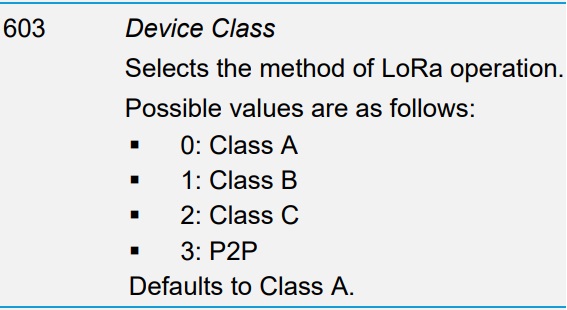
On the RM126x loaded with the AT Interface firmware, the Class device is configurable in the S Register 603 :


It is indeed possible to engage a Class change with AT Commands on the fly but once an S Register is changed, it must be followed by an AT&W to save the new configuration and then ATZ to reset the device. The Class device change will take effect once the RM126x will be reset so you'll have to re-join the LoRaWAN Network Server by issuing an AT+JOIN. It is advised to also engage in parallel the Class device change on the LoRaWAN Network Server and leverage the RM126x Join Sequence to apply the Class change on both sides.

Can I really expect 15 km distance transmission using LoRaWAN in my day to day application operation?

All Ezurio LoRa products should be referred as LoRaWAN as they all supports its protocol. LoRaWAN protocol make use of LoRa Chirp Spectrum Modulation within a license-free sub-gigahertz frequency band that allow to transmit regularly small packets up to 15km. 

It’s important to consider that 15km can only be achieved within absolute best conditions, some of which would be an outdoor “line of sight” transmission, interference free environment, ideal humidity/temperature, highest Spreading Factor, ect… Such range magnitude cannot represent any “real world” distance transmission and shouldn’t be expected by default.

What Error 14 means when trying to start an RM126x P2P session?

As per the User Guide RM126x AT Interface Application, an Error 14 stand for "Command cannot be processed in current state" :


As soon as AT+P2PS is issued (to start a P2P session), the system automatically check all parameters entered to see if your intended P2P network comply with regional regulatory enforcements. 

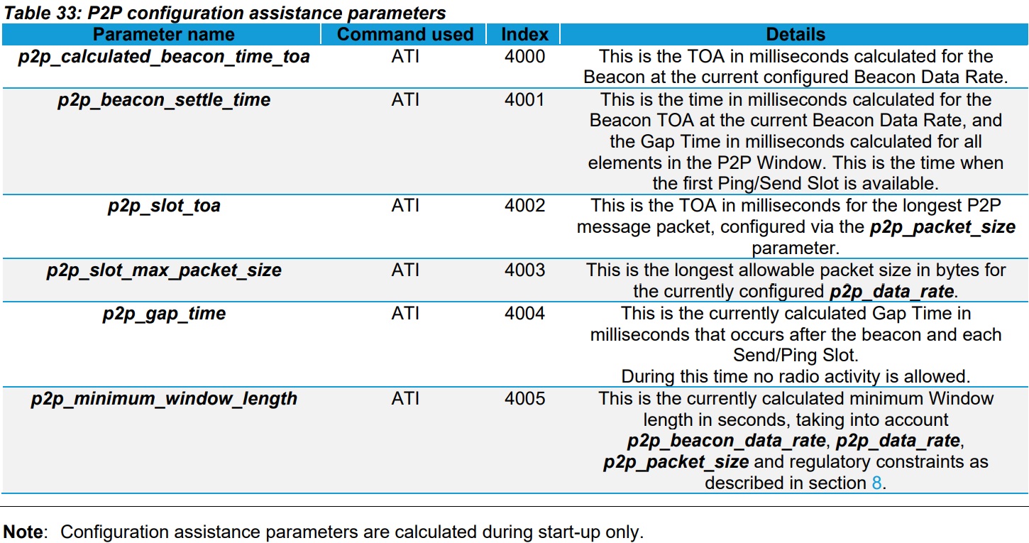
In general, ATI commands will provide useful information to correct and optimize your P2P configuration :


If an Error 14 comes up it likely means that your actual Window Length is too short and needs to be extended. A good way to know if your Window Length is adequate before starting a P2P session is to check the p2p_minimum_window_length by issuing an ATI 4005 and adapt your Window Length consequently.

How to lower the latency in my RM126x P2P network in Europe?

The RM126x P2P mode implements LoRaWAN standards to broadcast packet between peers over long distance. This approach allows regulatory certification achieved for the LoRaWAN modes of operation of the RM126x to be applied to the P2P mode. It means that customers can develop their P2P application without fearing to be be outside of any regulatory enforcements. 

In Europe the limiting factor for latency will be duty cycle enforcement of 1%. The minimum latency time to broadcast messages within a P2P network will be mainly a function of the Window Length, which is the time between two consecutives beacon generated by Device 0. As Window Length increases, it increases the latency to send messages. In other words : The longer the Window Length and the longer your devices will be waiting for sending a message.

The Window Length will be impacted by following parameters :

1) Network Size

2) Packet Size

3) Data rate (Message and Beacon)


The right configuration for a given application will always be a trade-off but in order to transfer packets more often, you'll need to :

1) Limit the number of device within a P2P network (up to 64 max).

2) Reduce the Time On Air (TOA) by sending shorter message packets. 

3) Make sure that Beacon and Message Data Rates match and both use the lower possible value.


More information can be found into Application Note - P2P User Guide - RM126x Series.

Is there a programming way to differentiate RM126x variant if I develop my own firmware?

The RM126x is based on the SX126x Lora radio from Semtech. Unfortunately, they didn't include any internal change between the SX1261 and SX1262 that would allow to differentiate them programmatically.

It is hence not possible to know the difference between the RM1261 and RM1262 by software only.

A workaround could be to leverage your own design board and add a pull up / pull down resistor on one of the spare GPIOs to indicate which variant it is.

How RM1261 P2P message channels and duty cycle are managed in Europe?

In Europe, the RM1261 P2P frequency channels will be divided as follows :
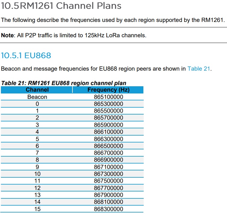

Within an RM126x P2P network, maximum number of devices allowed is 64. In Europe, each device will be attributed with one channel for broadcasting messages. The only exception will be for Device 0 which uses two channels : one for the Beacon and another one for sending messages.

Each new RM1261 that integrates the same P2P network will be attributed with a specific channel, but because there can be more devices than channels (64 device maximum vs 16 channels available), two devices can share a same channel as follows  :

Device 0 <===> Channel 0

Device 1 <===> Channel 1

Device 2 <===> Channel 2

Device 3 <===> Channel 3

Device 4 <===> Channel 4

Device 5 <===> Channel 5

Device 6 <===> Channel 6

Device 7 <===> Channel 7

Device 8 <===> Channel 8

Device 9 <===> Channel 9

Device 10 <===> Channel 10

Device 11 <===> Channel 11

Device 12 <===> Channel 12

Device 13 <===> Channel 13

Device 14 <===> Channel 14

Device 15 <===> Channel 15

Device 16 <===> Channel 0

Device 17 <===> Channel 1

Device 18 <===> Channel 2

Device 8 <===> Channel 3

Device 9 <===> Channel 4

Device 10 <===> Channel 5

...


It's important to keep in mind that our RM126x P2P feature is entirely covered by RM126x RF certification and sub-gigahertz country regulation. The way that P2P firmware in Europe calculates its duty cycle limitation is per channel used and not per device. Which means when 2 devices - within the same P2P network - share the same channel, they will also share its duty cycle of 1%, it means that both devices will be limited to 0.5% each.

The P2P firmware will automatically adjust its Window Length in regards to the p2p_network_size value. A good way to check the minimum Window Length allowable is to issue ati 4005 before launching a P2P session.

In the case of multiple RM1261 share the same channel, the system will increase the Window Length to make sure it satisfies duty cycle enforcement. 
When using RM126x P2P mode, can I queue multiple messages to be sent?

No, not in the initial release of firmware. Only a single message can be submitted for transmission. If subsequent messages are submitted, they will overwrite the existing message until it has been transmitted.

This might not be an issue for event based reporting but could be an issue if multiple messages or packets need to be sent in quick succession.

We will be adding extra functionality to better manage message queuing in time. Please check the firmware release notes for fuirther information or contact support@ezurio.com

When using RM126x P2P mode, what does Class: [Fail] error message mean?

The RM126x P2P mode uses a beacon at the start of a frame to synchronise the devices in the network. Device 0 is always the device that generates the beacon and all other devices listen for the beacon. In a device other than device 0 fails to receive the beacon then it will return the Class: [Fail] error message.

Commons reasons for seeing this error might include

  • Device 0 has not joined the network
  • Device 0 is out of range of the device seeing the error
  • The network has been incorrectly configured, for example more than the defined number of devices on the network