RM126x Ultra-Low Power LoRaWAN Module
Recommended for New Design (RND)

Overview

Now available: The LR 11 868MHz and LR 11 915 MHz click boards, powered by our RM126x modules!

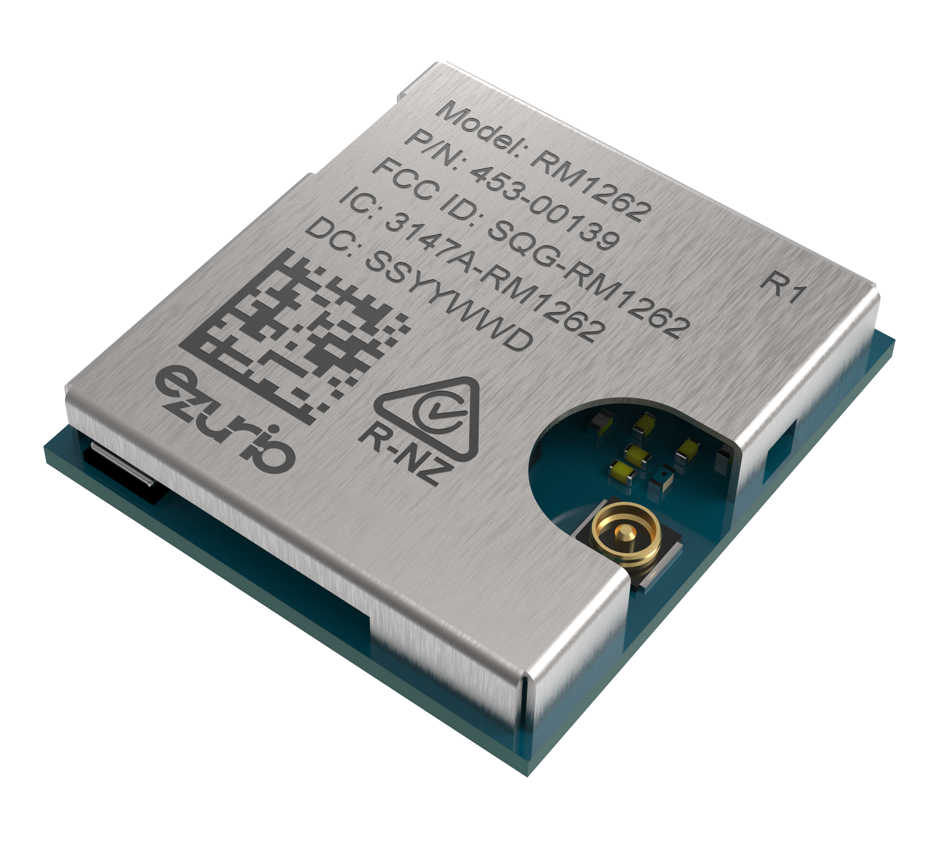
The Ezurio RM126x series of modules (RM1261 and RM1262) is based on Silicon Labs EFR32 SoC and the Semtech SX126x radio. They provide a low power, long range solution for you to easily develop your LoRaWAN implementation. The RM126x series supports LoRaWAN classes A, B and C,  and also includes a LoRa Point to Point (LoRa P2P) capability which enables you to create your own private ultra-long range radio network between two RM126x modules.

The RM126x series modules are small form factor PCB modules with a built in MHF4 connector, TCXO and a DC-DC converter. The module is designed to operate in both hosted and hostless modes.

  • Hosted Mode – When connected to an external microcontroller, it can be simply and easily programmed with our AT command set.
  • Hostless Mode – Utilizing the powerful Cortex-M33 core which includes 512kB flash and 32K of RAM. Full support is offered by Silicon Labs' Simplicity Studio for development purposes with a range of sample applications being offered by Ezurio to simplify customer development.
  • Small Form Factor – 14mm x 13mm PCB module designed for compact IoT devices.
  • LoRa P2P Communication – Enables you to create your own proprietary wireless network.
  • Quick to market - Built in TCXO, DC-DC converter and on board MHF4 antenna connector.
  • Ultra-Low Power Consumption - Years of use on a single battery.
  • Qualified Ezurio Sub Ghz Antennas - Certified to work with Ezurio Sub-GHz FlexPIFA, Sub-GHZ i-FlexPIFA and Sub-GHz Flexdipole antenna. 
  • LoRaWAN Certified - RM1261 and RM1262 (Test Reports)

Buy Now

0 in Ezurio stock
QtyUnit Price
1$0.00000
50$0.00000
100$0.00000
Seller Stock Buy
DigiKey 53 in stock Buy
Mouser 33 in stock Buy
Avnet 15 in stock Buy
Farnell 11 in stock Buy
Arrow Electronics 5 in stock Buy
Future Electronics 0 in stock Buy
Arrow Electronics 250 in stock Buy
Avnet 250 in stock Buy
Farnell 250 in stock Buy
Mouser 149 in stock Buy
Future Electronics 0 in stock Buy
DigiKey 1672 in stock Buy
Avnet 1000 in stock Buy
Mouser 903 in stock Buy
Arrow Electronics 0 in stock Buy
Future Electronics 0 in stock Buy
DigiKey 30 in stock Buy
Mouser 20 in stock Buy
Avnet 15 in stock Buy
Farnell 9 in stock Buy
Arrow Electronics 5 in stock Buy
Future Electronics 0 in stock Buy
Avnet 250 in stock Buy
Farnell 221 in stock Buy
Mouser 213 in stock Buy
Future Electronics 0 in stock Buy
DigiKey 1755 in stock Buy
Avnet 1000 in stock Buy
Mouser 945 in stock Buy
Arrow Electronics 0 in stock Buy
Future Electronics 0 in stock Buy

Now Available: RM126x DVKs

Start prototyping your next IoT application today.

The RM1262 kit contains:

  • RM1262 DVK Board (exposes all available HW interfaces)
  • 1x USB cable
  • 1x Ezurio i-FlexPIFA antenna (902-928 MHz)

The RM1261 kit contains:

  • RM1261 DVK Board (exposes all available HW interfaces)
  • 1x USB cable
  • 2x Ezurio i-FlexPIFA antenna (863-870 MHz and 902-928 MHz)
453-00140-md.png

Development Kits

  • 453-00139-K1

    453-00139-K1

    Recommended for New Design (RND)

    Development Kit, RM1262, SX1262, MHF4

    Learn More
  • 453-00140-K1

    453-00140-K1

    Recommended for New Design (RND)

    Development Kit, RM1261, SX1261, MHF4

    Learn More

Certified Antennas

Specifications

Chipset
Silicon Labs EFR32
Dimension (Length - mm)
14
Dimension (Width - mm)
13
Dimension (Height - mm)
2
Connector
MHF4
Certifications
RM1262: FCC, ISED, AS/NZS
RM1261: EU, UKCA, NCC, MIC, IN
Data Rate
LoRa 125kHz
LoRa 250kHz
LoRa 500kHz
FSK 50kbps (as per RP002-1.0.3 )
Frequency Range (Max)
870 MHz
Frequency Range (Min)
863 MHz
Frequency Range 2 (Max)
928 MHz
Frequency Range 2 (Min)
902 MHz
LoRa Version Class
Version V1.0.4 LoRa MAC Class A,B & C
Operating Temp (Max) (°C)
+85 °C
Operating Temp (Min) (°C)
-40 °C
Part NumberPrice @ 1kChipset (MCU)Chipset (Wireless)ConnectorFrequency Range (Max)Frequency Range (Min)Frequency Range 2 (Max)Frequency Range 2 (Min)PackagingPower Consumption (Tx)Product Type
453-00139C
453-00139C
Active
Buy Options
N/ASilicon Labs EFR32 Semtech SX1262 MHF4 928 MHz902 MHzCut Tape Up to 22dBm Embedded Module
453-00139R
453-00139R
Active
Buy Options
N/ASilicon Labs EFR32 Semtech SX1262 MHF4 928 MHz902 MHzTape / Reel Up to 22dBm Embedded Module
453-00140C
453-00140C
Active
Buy Options
N/ASilicon Labs EFR32 Semtech SX1261 MHF4 870 MHz863 MHz928 MHz902 MHzCut Tape Up to 14dBm Embedded Module
453-00140R
453-00140R
Active
Buy Options
N/ASilicon Labs EFR32 Semtech SX1261 MHF4 870 MHz863 MHz928 MHz902 MHzTape / Reel Up to 14dBm Embedded Module

Documentation

Name Part Type Last Updated
Product Brief - RM126X Series All Product Brief 05/14/2024
Datasheet - RM126x LoRaWAN Module All Datasheet 04/10/2024
RM126X SCH Symbol (Altium format) All Technical Drawings 06/14/2024
RM126X PCB footprint (DXF and Altium format) All Technical Drawings 06/14/2024
Schematic & PCB Assembly - DVK-RM1262 Devboard All Technical Drawings 06/14/2024
Schematic & PCB Assembly - DVK-RM1261 Devboard All Technical Drawings 06/14/2024
3D Model - RM1261, SX1261, MHF4 (453-00140) All Technical Drawings 06/14/2024
3D Model - RM1262, SX1262, MHF4 (453-00139) All Technical Drawings 06/14/2024
User Guide - RM126x Development Kit All Documentation 10/17/2023
Application Note - Peripheral Interface Guide - Lyra, Lyra 24, and RM126x Series All Application Note 06/10/2024
Application Note - Using Radio Test Firmware - RM126x Series All Application Note 01/02/2024
ISED Canada Certifications - RM1262 All Certification 08/08/2023
AS/NZS Certifications - RM1262 All Certification 06/03/2024
EU Certifications - RM1261 All Certification 08/29/2024
NCC Certifications - RM1261 All Certification 08/08/2023
MIC Certifications - RM1261 All Certification 08/08/2023
India Certifications - RM1261 All Certification 08/08/2023
FCC Certifications - RM1262 All Certification 03/07/2024
Regulatory Information Guide - RM1262 Series All Certification 04/10/2024
Regulatory Information Guide - RM1261 Series All Certification 08/21/2024
User Guide - RM126x AT Interface Application All Documentation 08/06/2024
User Guide - Firmware Options and Upgrading - RM126x Series All Documentation 08/22/2023
Firmware - RM126x Series (GitHub) All Software 08/15/2023
Application Note - Configuring the EVK UART Baud Rate - Lyra 22/Lyra 24/RM126x All Application Note 09/15/2023
Quick Start Guide - AT Interface Application - RM126x Series All Documentation 05/21/2024
Application Note - P2P User Guide - RM126x Series All Application Note 05/21/2024
Application Note - Low Power Mode - RM126x Series All Application Note 12/06/2023
Application Note - C Code Development - RM126x Series All Application Note 01/23/2024
Release Notes - RM126x Series All Documentation 05/08/2024
LoRaWAN Certified - RM1261 Test Report All Certification 10/31/2024
LoRaWAN Certified - RM1262 Test Report All Certification 10/31/2024

FAQ

Can I send a binary stream in P2P Mode?

Sending binary stream is not supported, instead it is necessary to convert binary to hex (and vice-versa)

From User Guide - RM126x AT Interface Application (section 4.8.3 AT+P2PT)

"This command is used to send data to a peer. {data} is the data in hexadecimal format to be sent within quote characters."

Can I configure RM1261 to operate in the 9xx MHz range via AT commands?

No, it is not possible to configure the RM1261 module to operate in the 902-928 MHz range via software or AT commands. The RM1261 and RM1262 are hardware-specific, and users must select the correct hardware (RM1261 or RM1262) based on the regional frequency band in which they need to operate. Switching between these frequencies via firmware or software is not supported.

You can find more information in: EZ-GUIDE-ATInterface-RM126x_v1_6.pdf where you can find: 

ATS 611 command that sets the region of operation. 

 Possible values are as follows: 
         0: Unconfigured 

RM1261 only: 

        1: EU_EU868 
        2: UK_EU863_870 
        8: TAIWAN_AS923_1 
        9: JAPAN_AS923_1 
        11: INDIA_IN865_867 

RM1262 only: 

        3: USA_CANADA_US902_928 
        4: AUSTRALIA_AU915_928  
        5: AUSTRALIA_AS923_1  
        6: NEW_ZEALAND_AS923_1 
         7: NEW_ZEALAND_AU915_928

What data rates are available for LoRaWAN and p2p in RM1262 in US?

The DR0-DR4 are available for LoRaWAN and DR0-DR3 are available for p2p in US. 

No UART messages show up after adding USART0 through configurator in Simplicity Studio.

There’s a nice article at the link below describing the steps needed.


https://siliconlabs.my.site.com/community/s/article/Understanding-the-IO-Stream-module?language=en_US


What’s happening here is that the newly added UART takes ownership of the stdio so it no longer appears on the UART connected to the USB port, but on the newly added UART.


‘When the project is added one more IO Stream instances, please refer to the following code that the last initialized instance is used as the default IO stream’.


To correct this, the following can be added to the application.


  // Initialize Silicon Labs device, system, service(s) and protocol stack(s).

  // Note that if the kernel is present, processing task(s) will be created by

  // this call.

  sl_system_init();


  // Redirect stdio

  sl_iostream_t *sl_iostream = sl_iostream_get_handle("hostcom");

  sl_iostream_set_default(sl_iostream);


  // Initialize the application. For example, create periodic timer(s) or

  // task(s) if the kernel is present.

  app_init();


Essentially what’s happening is that one UART is used to send data from underlying printf statements – the above change is used to set the destination UART for this back to the USB based serial port.

Why Epoch time is required for RM126x p2p in US?

FCC Radio regulatory standard (applied to RM1262) is 47 CFR FCC Part 15.247 FCC CFR FCC -

https://www.ecfr.gov/current/title-47/chapter-I/subchapter-A/part-15#15.247 -

We declared LoRa 125kHz as FHSS, so the Epoch Period = 0.4 x N where N minimum is 50, for RM1262(LoRa 125kHz) we used N=64.  


For more information, refer to  FR2D2902_RM1262_FCC 15.247 LoRa_902.3 ~ 914.9MHz (FHSS_125k).pdf in https://www.ezurio.com/documentation/fcc-certifications-rm1262 

"Debug access is locked" message popped up while programming custom C application.

RM126x module ships with a debug lock configuration to protect the module from readback to protect its security keys. We don’t really broadcast the secure nature of the bootloader and the application because we don’t want to publicize it to hackers and vulnerability scalpers.


If you want to write your own firmware, you need to enable debug, which will erase the part. Note you also need to create your own bootloader if you are writing your own code, the RM126x bootloader also implements some of the security mechanisms. 


Refer to the link below for how to do this using Simplicity Studio. 

https://community.silabs.com/s/question/0D58Y00008z2ZLTSA2/how-unlock-efr32bg12-using-jlink-commander?language=en_US

How can I send downlink LoRaWAN message from AWS?

You can queue downlink message from the device page. For detailed information, refer to https://docs.aws.amazon.com/iot-wireless/latest/developerguide/lorawan-downlink-queue.html

Is it safe to test P2P functionality with RM126x modules when they are in close proximity?

When RM126x modules are in close proximity (within 4-5 feet) during P2P testing, setting the Tx power to its lowest setting of 1 dBm is crucial to prevent RF energy saturation on the receiver. Higher Tx power could damage the radios, potentially causing irreparable harm.

Is it safe to set up a LoRaWAN communication between a module and a gateway in close proximity?

While it is generally safe to have the RM126x module and the gateway in close proximity during LoRaWAN communication, it is advisable to maintain a few meters of distance between any LoRaWAN end devices and the gateway. This helps ensure optimal performance and avoids potential issues related to signal interference.


What tools are required for RM126x module Hosted Mode vs Hostless Mode?

Hosted mode: when connected to an external microcontroller, the module can be easily operated using our AT command set.

Hostless mode: Simplicity Studio from Silicon Labs provides full support for development (C Development), while we offer a variety of sample applications to streamline customer development. 

Finally feel free to check our User Guide - Firmware Options and Upgrading - RM126x Series that shows and explains all available firmware options and upgrade methods for our RM126x LoRaWAN modules

Which LoRa / LoRaWAN Basics Modem (LBM) stack and software library version is the AT Interface app for the RM126x series based on?

LoRa Basics Modem (LBM) is an open-source LoRaWAN stack and software library that can run on external MCUs. It for example enables worldwide interoperability in the ISM sub-GHz and 2.4 GHz bands and is broadly used by many companies in their LoRaWAN end-node products.

Our AT Interface application and implementation for the RM126x series is utilizing the LoRa Basics Modem SDK version 2.0.1. It is developed and maintained by the Semtech Corporation and also publicly available on GitHub at https://github.com/Lora-net/SWSD001/tree/v2.0.1.

Do you provide support for the RM126x and Lyra development boards through the Simplicity Studio 5 Software & IDE?

Yes, indeed we do. Similar like with other Silicon Labs based devices which you may have worked before already. Currently, all below mentioned RM126x and Lyra (22) + 24 development boards are automatically recognized and added to the “Debug Adapters” list once you connect them to your PC. They are displayed and found on the (Welcome) Launcher page within Simplicity Studio 5 – as usual. Simply speaking: This would be the starting point if you want to develop custom LoRaWAN / BLE applications in C when using our modules.

RM126x Series

  • Ezurio RM1261 Development Kit (BRD2900A Rev A00),
  • Ezurio RM1262 Development Kit (BRD2901A Rev A00).

Lyra 24 Series

  • Ezurio Lyra 24P 10dBm (Built-in) Ant Development Kit (BRD2902A Rev A00),
  • Ezurio Lyra 24P 20dBm (Built-in) Ant Development Kit (BRD2904A Rev A00),
  • Ezurio Lyra 24P 20dBm (RF) Pin Development Kit (BRD2903A Rev A00),
  • Ezurio Lyra 24S 10dBm Development Kit (BRD2905A Rev A00).

Lyra (22) Series

  • Ezurio Lyra P Development Kit (BRD4330A Rev A00),
  • Ezurio Lyra S Development Kit (BRD4331A Rev A00).

What sort of power consumption should I expect when using Laird RM126x P2P mode?

LoRaWAN has three end device class modes

Class A devices transmit and then open a receive window and outside of these events the radio can be switched off to minimise power consumption. Class A uses the least amount of power

Class B allows for scheduled receive windows, so that the network server will know when the device is awake and able to accept a downlink.

Class C keeps the device radio on permanently , meaning it is able to receive a downlink at any time from the network server. Class C uses the most power

Laird LoRa P2P mode can be thought as working like a hybrid of the above modes. Because it makes use of a beacon, to allow devices to synchronise with dedicated transmit and receive slots, the power consumption will be most like a class B LoRaWAN device as the radio will be on every time the device slot comes around. P2P mode can initially behave like a class C device when looking for a beacon.

Exact power consumption will be specific to an individual use case and it is advised to measure the power consumption for your particular use case but peak consumption values can be found in the datasheet.


Can I switch the RM126x LoRaWAN Class device on the fly?

The decision to switch between two LoRaWAN Class device is use-case specific and it needs to be initiated and proceed from both the end-device application layer and the LoRaWAN Network Server. It's good mentioning this process isn't managed at the LoRaWAN protocol level.

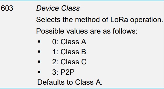
On the RM126x loaded with the AT Interface firmware, the Class device is configurable in the S Register 603 :


It is indeed possible to engage a Class change with AT Commands on the fly but once an S Register is changed, it must be followed by an AT&W to save the new configuration and then ATZ to reset the device. The Class device change will take effect once the RM126x will be reset so you'll have to re-join the LoRaWAN Network Server by issuing an AT+JOIN. It is advised to also engage in parallel the Class device change on the LoRaWAN Network Server and leverage the RM126x Join Sequence to apply the Class change on both sides.

Can I really expect 15 km distance transmission using LoRaWAN in my day to day application operation?

All Ezurio LoRa products should be referred as LoRaWAN as they all supports its protocol. LoRaWAN protocol make use of LoRa Chirp Spectrum Modulation within a license-free sub-gigahertz frequency band that allow to transmit regularly small packets up to 15km. 

It’s important to consider that 15km can only be achieved within absolute best conditions, some of which would be an outdoor “line of sight” transmission, interference free environment, ideal humidity/temperature, highest Spreading Factor, ect… Such range magnitude cannot represent any “real world” distance transmission and shouldn’t be expected by default.

What Error 14 means when trying to start an RM126x P2P session?

As per the User Guide RM126x AT Interface Application, an Error 14 stand for "Command cannot be processed in current state" :


As soon as AT+P2PS is issued (to start a P2P session), the system automatically check all parameters entered to see if your intended P2P network comply with regional regulatory enforcements. 

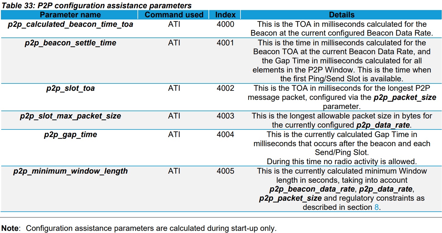
In general, ATI commands will provide useful information to correct and optimize your P2P configuration :


If an Error 14 comes up it likely means that your actual Window Length is too short and needs to be extended. A good way to know if your Window Length is adequate before starting a P2P session is to check the p2p_minimum_window_length by issuing an ATI 4005 and adapt your Window Length consequently.

How to lower the latency in my RM126x P2P network in Europe?

The RM126x P2P mode implements LoRaWAN standards to broadcast packet between peers over long distance. This approach allows regulatory certification achieved for the LoRaWAN modes of operation of the RM126x to be applied to the P2P mode. It means that customers can develop their P2P application without fearing to be be outside of any regulatory enforcements. 

In Europe the limiting factor for latency will be duty cycle enforcement of 1%. The minimum latency time to broadcast messages within a P2P network will be mainly a function of the Window Length, which is the time between two consecutives beacon generated by Device 0. As Window Length increases, it increases the latency to send messages. In other words : The longer the Window Length and the longer your devices will be waiting for sending a message.

The Window Length will be impacted by following parameters :

1) Network Size

2) Packet Size

3) Data rate (Message and Beacon)


The right configuration for a given application will always be a trade-off but in order to transfer packets more often, you'll need to :

1) Limit the number of device within a P2P network (up to 64 max).

2) Reduce the Time On Air (TOA) by sending shorter message packets. 

3) Make sure that Beacon and Message Data Rates match and both use the lower possible value.


More information can be found into Application Note - P2P User Guide - RM126x Series.

Is there a programming way to differentiate RM126x variant if I develop my own firmware?

The RM126x is based on the SX126x Lora radio from Semtech. Unfortunately, they didn't include any internal change between the SX1261 and SX1262 that would allow to differentiate them programmatically.

It is hence not possible to know the difference between the RM1261 and RM1262 by software only.

A workaround could be to leverage your own design board and add a pull up / pull down resistor on one of the spare GPIOs to indicate which variant it is.

How RM1261 P2P message channels and duty cycle are managed in Europe?

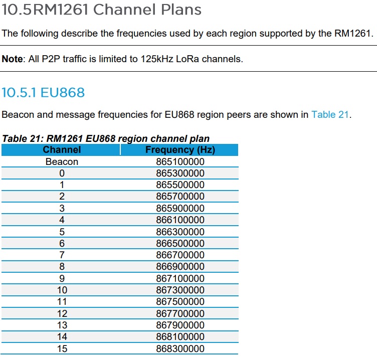
In Europe, the RM1261 P2P frequency channels will be divided as follows :


Within an RM126x P2P network, maximum number of devices allowed is 64. In Europe, each device will be attributed with one channel for broadcasting messages. The only exception will be for Device 0 which uses two channels : one for the Beacon and another one for sending messages.

Each new RM1261 that integrates the same P2P network will be attributed with a specific channel, but because there can be more devices than channels (64 device maximum vs 16 channels available), two devices can share a same channel as follows  :

Device 0 <===> Channel 0

Device 1 <===> Channel 1

Device 2 <===> Channel 2

Device 3 <===> Channel 3

Device 4 <===> Channel 4

Device 5 <===> Channel 5

Device 6 <===> Channel 6

Device 7 <===> Channel 7

Device 8 <===> Channel 8

Device 9 <===> Channel 9

Device 10 <===> Channel 10

Device 11 <===> Channel 11

Device 12 <===> Channel 12

Device 13 <===> Channel 13

Device 14 <===> Channel 14

Device 15 <===> Channel 15

Device 16 <===> Channel 0

Device 17 <===> Channel 1

Device 18 <===> Channel 2

Device 8 <===> Channel 3

Device 9 <===> Channel 4

Device 10 <===> Channel 5

...


It's important to keep in mind that our RM126x P2P feature is entirely covered by RM126x RF certification and sub-gigahertz country regulation. The way that P2P firmware in Europe calculates its duty cycle limitation is per channel used and not per device. Which means when 2 devices - within the same P2P network - share the same channel, they will also share its duty cycle of 1%, it means that both devices will be limited to 0.5% each.

The P2P firmware will automatically adjust its Window Length in regards to the p2p_network_size value. A good way to check the minimum Window Length allowable is to issue ati 4005 before launching a P2P session.

In the case of multiple RM1261 share the same channel, the system will increase the Window Length to make sure it satisfies duty cycle enforcement. 

When using RM126x P2P mode, do the beacon and data rates need to match?

No, the beacon and data rates can be different but at the time of writing there is no benefit from the two data rates being different. If in doubt set them to the same data rate,

When using RM126x P2P mode, can I queue multiple messages to be sent?

No, not in the initial release of firmware. Only a single message can be submitted for transmission. If subsequent messages are submitted, they will overwrite the existing message until it has been transmitted.

This might not be an issue for event based reporting but could be an issue if multiple messages or packets need to be sent in quick succession.

We will be adding extra functionality to better manage message queuing in time. Please check the firmware release notes for fuirther information or contact support@ezurio.com

When using RM126x P2P mode, what does Class: [Fail] error message mean?

The RM126x P2P mode uses a beacon at the start of a frame to synchronise the devices in the network. Device 0 is always the device that generates the beacon and all other devices listen for the beacon. In a device other than device 0 fails to receive the beacon then it will return the Class: [Fail] error message.

Commons reasons for seeing this error might include

  • Device 0 has not joined the network
  • Device 0 is out of range of the device seeing the error
  • The network has been incorrectly configured, for example more than the defined number of devices on the network

How can I build my own UART DFU utility (also known as uart_dfu or bt_host_uart_dfu) under Windows and/or Linux?

The UART DFU utility (also known as uart_dfu or bt_host_uart_dfu) is provided by Silicon Labs. It is a console application which enables firmware updates over a serial UART connection.

This host example is available in C and part of the official Gecko SDK (GSDK). In Windows the application can be built using, for example, MinGW or Cygwin. Under Linux or Mac the program can be compiled with the GCC toolchain.

Before starting, please make sure that Simplicity Studio 5 is installed on your Windows or Linux system. The Gecko SDK − 32-bit and Wireless MCUs technology / software component is mandatory, and the latest available version can be downloaded through the Installation Manager in Simplicity Studio at any time if needed.

Windows

You can either find the UART DFU host example under C:\SiliconLabs\SimplicityStudio\v5\developer\sdks\gecko_sdk_suite\\app\bluetooth\example_host\uart_dfu or C:\Users\\SimplicityStudio\SDKs\gecko_sdk\app\bluetooth\example_host\bt_host_uart_dfu. Depending on your Simplicity Studio 5 installation and configuration paths may be different. Otherwise, try to search for the uart_dfu folder on your Windows system.

  1. Download the latest available Mingw-w64 compiler binaries for Windows and extract them e.g. under C:\mingw64 with 7-Zip. In our example we are using the x86_64-12.2.0-release-posix-seh-rt_v10-rev0.7z release on a Windows 10 Enterprise (21H2) x64 system.
  2. Search under Windows for the Edit environment variables for your account shortcut or quick access item. Under User Variables, modify the Path variable. Click Edit and New and add your MinGW-w64 installation path to it. In our example it is C:\mingw64\bin. The bin folder is very important here. Click OK and save your environment variables. There is no need to reboot your computer. All environment variable changes are applied immediately.
  3. Next open a Command Prompt (cmd.exe) window, update the environment variables with the set PATH=C:\mingw64\bin;%PATH% command and navigate into the UART DFU host example folder. In our example we are using the cd C:\Users\Laird\SimplicityStudio\SDKs\gecko_sdk\app\bluetooth\example_host\bt_host_uart_dfu command.
  4. Now build the UART DFU host example by entering the mingw32-make command. This will take a few seconds. The bt_host_uart_dfu.exe binary can be found in a subfolder called "exe" once successfully completed.
  5. Use the cd exe command to navigate into the exe directory. For testing, enter bt_host_uart_dfu.exe which should print a similar usage information text as following: bt_host_uart_dfu.exe -t | -u [-b ] [-f] [-l ] [-h]

Linux

You can either find the UART DFU host example under /opt/SiliconLabs/SimplicityStudio/v5/developer/sdks/gecko_sdk_suite//app/bluetooth/example_host/uart_dfu or //SimplicityStudio/SDKs/gecko_sdk/app/bluetooth/example_host/bt_host_uart_dfu. Depending on your Simplicity Studio 5 installation and configuration paths may be different. Otherwise, try to search for the uart_dfu folder on your Linux filesystem.

  1. Make sure that the build-essential package is installed on your Linux system with the sudo apt install build-essential command. In our example we are using a Ubuntu 22.04 LTS x64 system.
  2. Next open a Terminal window and navigate into the UART DFU host example folder. In our example we are using the cd /root/SimplicityStudio/SDKs/gecko_sdk/app/bluetooth/example_host/bt_host_uart_dfu command.
  3. Now build the UART DFU host example by entering the make command. This will take a few seconds. The bt_host_uart_dfu binary can be found in a subfolder called "exe" once successfully completed.
  4. Use the cd exe command to navigate into the exe directory. For testing, enter ./bt_host_uart_dfu which should print a similar usage information text as following: bt_host_uart_dfu -t | -u [-b ] [-f] [-l ] [-h]

Become an Ezurio Customer to Gain Exclusive Access to Our Design Experts

  • Antenna Scans
  • Antenna selection and placement
  • Custom antenna design
  • Worldwide EMC testing / certifications
  • Embedded RF hardware / firmware design
  • Cloud architecture and integration
  • Mobile application development
  • Product & Industrial Design

Talk to an Expert

Distributors

Distributor Phone Number Region Website
Arrow Electronics 1-855-326-4757
+44 2039 365486
APAC, North America, South America, EMEA Website
Avnet 1-480-643-2000
+44 1628 512900
APAC, North America, South America, EMEA Website
Braemac Australia, New Zealand, South East Asia +61 2 9550 6600
+64 9 477 2148
APAC Website
Cal-Chip Connect 1-215-942-8900
North America Website
DigiKey 1-800-344-4539
North America, South America, APAC, EMEA Website
EBV Elektronik EMEA Website
Farlink Technology China, Hong Kong +86 13266922199
APAC Website
Farnell 1-800-936-198
+44 3447 11 11 22
EMEA Website
Future Electronics 1-800-675-1619
1-514-428-8470
North America, South America, APAC, EMEA Website
Glyn +49-6126-590-0
EMEA Website
Hy-Line Germany Only +49 89 614 503 0
EMEA Website
Jetronic China, Hong Kong and Taiwan 852-27636806 
APAC Website
Laird Connectivity 1-847-839-6925
+44 1628 858941
North America, South America, APAC, EMEA Website
M2M Germany +49-6081-587386-0
EMEA Website
Martinsson +46 8 7440300
EMEA Website
McCoy South East Asia +65 6515 2988
APAC Website
Mouser 1-800-346-6873
+44 1494 427500
North America, South America, APAC, EMEA Website
RS Components +852-2421-9898
+44 3457-201201
North America, South America, APAC, EMEA Website
Ryoyo Japan +81-3-3543-7711
APAC Website
Solsta UK Only +44 (0) 1527 830800
EMEA Website
Supreme Components International India, South East Asia +65 6848-1178
APAC Website
Symmetry Electronics 1-866-506-8829
North America Website
Tekdis Australia and New Zealand +61 3 8669 1210
APAC Website
Telsys +972 3 7657666
EMEA Website
WPG +44 1628 958460
EMEA Website