/filters:background_color(white)/2025-02/Nitrogen%2093%20NX611%20front-1port.png)
Scope
This document describes key hardware aspects of Ezurio’s Nitrogen93 SMARC system-on-module which is based on the i.MX 93 processor family and the Sona IF573 Wi-Fi/BT combo radio. Data in this document is drawn from several sources and includes information found in the documentation for NXP’s i.MX 93 and our Sona IF573.
Note: Information in this document is subject to change. Contact us for the most updated version of this document.

Introduction
Overview
This document describes key hardware aspects of the Nitrogen93 SMARC. This document is intended to assist device manufacturers and related parties with the integration of this radio into their host devices. Data in this document is drawn from several sources. For full documentation on the Nitrogen93 SMARC, visit:
https://www.ezurio.com/nitrogen93-smarc
General Description
The Nitrogen93 SMARC is an integrated platform solution with the NXP I.MX 93 processor that integrates a dual Arm® Cortex®-A55 cluster operating up to 1.7 GHz, a 250 MHz Arm Cortex-M33 and pre-certified tri-band 8 02.11 a/b/g/n/ac/ax WLAN plus dual-mode Bluetooth® 5.4 L ow Energy module.
The Arm® Cortex®-A55 cores bring best-in-class performance and energy efficiency to Linux-based edge applications and the Arm Cortex-M33 processor can perform time-critical real-time compute and control.
The processor also embeds the Arm® Ethos™-U65 microNPU, a dedicated neural processing unit (NPU) which delivers a combination of performance and efficiency with an optimized footprint that enables developers to create high-performance, cost-effective and energy-efficient ML applications. Also, the built-in Arm Cortex M33 in conjunction with the NPU can be used for low-power wake-word detection.
Additionally, it offers the latest high-speed interfaces for connectivity and fast data transfer with 2x USB 2.0, 3x SD/SDIO 3.01, 2x Gbit Ethernet with EEE, AVB, IEEE 1588, in addition to 2x CAN-FD interfaces. The memory interfaces supported are 16-bit LPDDR4X and eMMC 5.1.
The module also includes a 2-lane MIPI-CSI camera interface capable of supporting 1080p60 resolution as well as a 4-lane MIPI-DSI output capable of supporting 1080p60 resolution or a 4-lane LVDS one supporting 720p60 for multimedia applications.
The i.MX 93 family implements security via NXP’s EdgeLock® secure enclave, a preconfigured, self-managed and autonomous security subsystem. EdgeLock eases the complexity of implementing robust, device-wide security intelligence for IoT applications through autonomous management of critical security functions, such as root of trust, run-time attestation, trust provisioning, secure boot, key management and cryptographic services while also simplifying the path to industry-standard security certifications.
The Nitrogen93 SMARC includes the Sona IF573 which is pre-calibrated and integrates the complete transmit/receive RF paths including bandpass filter, diplexer, switches, reference crystal oscillator, and power management units (PMU). Three RF connectors (MHF4) on the module provide the most flexibility for antenna selection, installation and performance. Two ports for WLAN and one dedicated for Bluetooth. Several high-performance antennas are certified with the Sona IF573 onboard the Nitrogen93 SMARC.
The Nitrogen93 SMARC has several product SKUs providing different eMMC and LPDDR4 memory configurations, see Ordering Information section.
This datasheet is subject to change. Please contact Ezurio for further information.
Errata
ERRATA1: Addition of Pull-Up Resistors for i2C Communication
Issue: In the current design of IMX93_SMARC REV 20, pull-up resistors were not included on the I2C_GP(S48,S49).
Impact: This omission affects the reliability of I2C communication, particularly at higher speeds.
Resolution: To address this issue, it is recommended to add pull-up resistors to the I2C_GP on the product's carrier board. Pull-up resistors should be of appropriate value to ensure proper signal integrity. The recommended value for pull-up resistors typically falls in the range of 2.2kΩ to 10kΩ, depending on factors such as bus capacitance and desired speed.
Action: Future revisions of the product should include pull-up resistors on the I2C lines as per the recommended values mentioned above.
Specification Summary
Processor / SoC / Chipset
| CPU | Dual Cortex®-A55 processors operation up to 1.8 GHz
Cortex®-M33 core platform operating up to 250 MHz
256 KB tightly coupled memory (TCM) |
| GPU | Graphics Engine: Pixel Pipeline (PxP)
|
| NPU | Arm® Ethos™-U65 microNPU
|
Radio Performance
| RF Output | RF output with MHF4 connector provides flexible external antenna selection for optimized performance for both Wi-Fi and BT |
Interfaces
| Physical Interfaces | SMARC 2.2 - 314 Pin Connector |
| Network Interfaces | Dependent on part - see Ordering Information |
| Display Interface | LCDIF Display Controller. Can drive any of two displays:
|
| Camera Interface | One 2-lane MIPI CSI-2 camera input:
|
| Audio Interface |
|
| Memory Interface |
|
| Image Sensor Interface (ISI) |
|
| Peripheral Interface | 48x Multifunction I/O lines |
|---|---|
| Ethernet |
|
| UART |
|
| USB |
|
| uSDHC |
|
| CAN |
|
| I2C |
|
| SPI |
|
Power
| Input Voltage | 5V (see Electrical Characteristics and Pinout ) |
| I/O Signal Voltage | 1.8V or 3.3V (see Electrical Characteristics and Pinout ) |
| Power Modes | OFF, READY, SNVS, RUN, STANDBY, PWRDN, PWRUP and FAULT_SD. See Power Modes. |
Mechanical
| Dimensions | 82 x 50 mm |
Software
| OS Support | Linux, U-Boot, Buildroot, FreeRTOS, QNS SDP, Yocto |
| Security |
|
Environmental
| Operating Temperature | 0 to +70C (Commercial Temp) -40 to +85C (Industrial Temp) |
| Lead Free | Lead-free and RoHS Compliant |
Certifications
| Regulatory Compliance | FCC/IC/CE/MIC/RCM/KCC |
Development
| Development Kit | Universal SMARC Carrier Board |
| Evaluation Kit | EZSMI-935-0216-00158-2-K2: 7-Inch Touchscreen Display / SMARC Carrier Board / i.MX 93 / 2GB / 16 GB eMMC / Sona NX611 Wi-Fi 6 and Bluetooth 5.4 / Antenna / Accessory Cables |
| Debug |
|
Warranty
| Warranty Terms | One Year Warranty |
Functional Descriptions
Power-Up Sequence and Timing
Boot Mode
The Nitrogen93 SMARC module contains a switch (SW1) connected to BOOT_MODE0 thus allowing to switch from internal fuses boot (eMMC by default) to USB serial downloader.
The other boot mode signals (BOOT_MODE[1-3]) are not exposed to the carrier as used for different functions (UART/I2S). But a BOM change can select a custom boot mode (see resistors R128 to R135).
This allows more combinations as shown in the following table.
Boot mode combinations
| BOOT_MODE [3:0] | BOOT CORE | BOOT MODE |
|---|---|---|
| 0000 | Cortex-A55 | Boot from Internal Fuses |
| 0001 | Cortex-A55 | Serial Download (USB1) |
| 0010 | Cortex-A55 | USDHC1 8-bit eMMC 5.1 (default) |
| 0011 | Cortex-A55 | USDHC2 4-bit SD 3.0 |
| 0100 | Cortex-A55 | FlexSPI Serial NOR |
| 0101 | Cortex-A55 | FlexSPI Serial NAND 2K |
| 0110 | Cortex-A55 | Infinite Loop Mode |
| 0111 | Cortex-A55 | Test Mode |
| 1000 | Cortex-M33 | LPB: Boot From Internal Fuses |
| 1001 | Cortex-M33 | LPB: Serial Downloader (USB1) |
| 1010 | Cortex-M33 | LPB: USDHC1 8-bit 1.8V eMMC 5.1 |
| 1011 | Cortex-M33 | LPB: USDHC2 4-bit SD 3.0 |
| 1100 | Cortex-M33 | LPB: FlexSPI Serial NOR |
| 1101 | Cortex-M33 | LPB: FlexSPI Serial NAND 2K |
| 1110 | Cortex-M33 | Infinite Loop Mode |
| 1111 | Cortex-M33 | Test Mode |
Hardware Architecture
Block Diagrams
The figure below shows the block diagram of the Nitrogen93 SMARC which contains the NXP i.MX 93 processor, PMIC (PCA9451A) and the Sona IF573 Wi-Fi/BT combo.
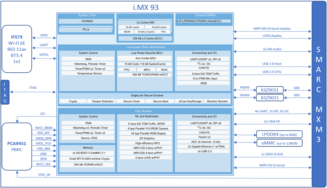
Detailed connections between the IF573 and the i.MX 93 are detailed in the Table below.
Sona IF573 to i.MX 93 Connections
| IF573 | i.MX 93 | |
|---|---|---|
| SDIO | SDIO_CLK/CMD/DATA[0:3] | SD3_CLK/SD3_CMD/SD3_DATA0-3 |
| UART | UART_RX/UART_TX/UART_CTS/UART_RTS | UART5 (DAP_TCLK/TMS/TDI/TDO) |
| CLK | SUSCLK | GPIO_IO24 (TMP3_CH3) |
| BT_EN | W_DISABLE2# | P0_4 (from U13 GPIO expander) |
| BT_IRQ | UART_WAKE# | P0_6 (from U13 GPIO expander) |
| WL_EN | W_DISABLE1# | P0_2 (from U13 GPIO expander) |
| WL_IRQ | SDIO_WAKE# | P0_3 (from U13 GPIO expander) |
Pin-Out and Pinmux Table
The following tables list the pin multiplexing (PIN-MUX) of the Nitrogen93 SMARC.
PO = Power Output, PI = Power Input, DI = Digital Input, DO = Digital Output, DIO = Bi-directional Digital Port, GND = Ground
NXP process has configurable internal Pull-up (PU) and pull-down (PD) resistor whose values are listed below. During a reset condition, the PU and PD state are pre-defined and cannot be changed.
Resistor characteristics
| Parameter | Conditions | Min | Typ | Max | Unit |
|---|---|---|---|---|---|
| Pull-up (PU) resistor | VDD=1.65 to 1.95V Temp=0 to 95℃ | 12 | 22 | 49 | kΩ |
| Pull-down (PD) resistor | 13 | 23 | 48 | kΩ | |
| Pull-up (PU) resistor | VDD=3.0 to 3.6V Temp=0 to 95℃ | 18 | 37 | 72 | kΩ |
| Pull-down (PD) resistor | 24 | 43 | 87 | kΩ |
Pin configuration for the i.MX is achieved using a suite of evaluation and configuration tools that assists users from initial evaluation to production software development. Users can download the tool from the NXP website: https://www.nxp.com/design/designs/config-tools-for-i-mx-applications-processors:CONFIG-TOOLS-IMX?tab=Design_Tools_Tab
Pinout table for Nitrogen93 SMARC edge connector (J2)
| SMARC Pin # | SMARC Pin Name | CPU PIN / Multiplexing (bold = default muxing) | I/O | I/O Level | Comments |
|---|---|---|---|---|---|
| P1 | SMB_ALERT# | P2_7 | DI | 1.8 to 5 V | From GPIO expander (U13) |
| P2 | GND | NA | - | NA | |
| P3 | CSI1_CK+ | NA | - | NA | |
| P4 | CSI1_CK- | NA | - | NA | |
| P5 | GBE1_SDP | NA | - | NA | |
| P6 | GBE0_SDP | NA | - | NA | |
| P7 | CSI1_RX0+ | NA | - | NA | |
| P8 | CSI1_RX0- | NA | - | NA | |
| P9 | GND | NA | - | NA | |
| P10 | CSI1_RX1+ | NA | - | NA | |
| P11 | CSI1_RX1- | NA | - | NA | |
| P12 | GND | NA | - | NA | |
| P13 | CSI1_RX2+ | NA | - | NA | |
| P14 | CSI1_RX2- | NA | - | NA | |
| P15 | GND | NA | - | NA | |
| P16 | CSI1_RX3+ | NA | - | NA | |
| P17 | CSI1_RX3- | NA | - | NA | |
| P18 | GND | NA | - | NA | |
| P19 | GBE0_MDI3- | TXRXM_D | DI/O | 1.8V | From KSZ9031 (U6) |
| P20 | GBE0_MDI3+ | TXRXP_D | DI/O | 1.8V | From KSZ9031 (U6) |
| P21 | GBE0_LINK100# | LED1 | DO | 3.3V | From KSZ9031 (U6) |
| P22 | GBE0_LINK1000# | LED2 | DO | 3.3V | From KSZ9031 (U6) |
| P23 | GBE0_MDI2- | TXRXM_C | DI/O | 1.8V | From KSZ9031 (U6) |
| P24 | GBE0_MDI2+ | TXRXP_C | DI/O | 1.8V | From KSZ9031 (U6) |
| P25 | GBE0_LINK_ACT# | LED1 | DO | 3.3V | From KSZ9031 (U6) |
| P26 | GBE0_MDI1- | TXRXM_B | DI/O | 1.8V | From KSZ9031 (U6) |
| P27 | GBE0_MDI1+ | TXRXP_B | DI/O | 1.8V | From KSZ9031 (U6) |
| P28 | GBE0_CTREF | TP9 | - | NA | Test point |
| P29 | GBE0_MDI0- | TXRXM_A | DI/O | 1.8V | From KSZ9031 (U6) |
| P30 | GBE0_MDI0+ | TXRXP_A | DI/O | 1.8V | From KSZ9031 (U6) |
| P31 | SPI0_CS1# | GPIO: GPIO2_IO07 SPI: LPSPI3_PCS1 CAM: MEDIAMIX_CAM_DATA01 CAM: MEDIAMIX_DISP_DATA03 SPI: LPSPI7_SCK UART: LPUART6_RTS_B I2C: LPI2C7_SCL FLEXIO: FLEXIO1_FLEXIO07 | DO | 1.8V | |
| P32 | GND | NA | - | NA | |
| P33 | SDIO_WP | P1_4 | DI | 1.8 or 3.3V | From GPIO expander (U13) |
| P34 | SDIO_CMD | USDHC: USDHC2_CMD ENET: ENET1_1588_EVENT0_IN I3C: I3C2_PUR I3C: I3C2_PUR_B FLEXIO: FLEXIO1_FLEXIO02 GPIO: GPIO3_IO02 CCM: CCMSRCGPCMIX_OBSERVE1 | DI/O | 1.8 or 3.3V | |
| P35 | SDIO_CD# | USDHC: USDHC2_CD_B ENET: ENET_QOS_1588_EVENT0_IN I3C: I3C2_SCL FLEXIO: FLEXIO1_FLEXIO00 GPIO: GPIO3_IO00 | DI | 1.8 or 3.3V | |
| P36 | SDIO_CK | USDHC: USDHC2_CLK ENET: ENET_QOS_1588_EVENT0_OUT I3C: I3C2_SDA FLEXIO: FLEXIO1_FLEXIO01 GPIO: GPIO3_IO01 CCM: CCMSRCGPCMIX_OBSERVE0 | DO | 1.8 or 3.3V | |
| P37 | SDIO_PWR_EN | USDHC: USDHC2_RESET_B TIMER: LPTMR2_ALT2 FLEXIO: FLEXIO1_FLEXIO07 GPIO: GPIO3_IO07 CCM: CCMSRCGPCMIX_SYSTEM_RESET | DO | 3.3V | |
| P38 | GND | NA | - | NA | |
| P39 | SDIO_D0 | USDHC: USDHC2_DATA0 ENET: ENET1_1588_EVENT0_OUT CAN: CAN2_TX FLEXIO: FLEXIO1_FLEXIO03 GPIO: GPIO3_IO03 CCM: CCMSRCGPCMIX_OBSERVE2 | DI/O | 1.8 or 3.3V | |
| P40 | SDIO_D1 | USDHC: USDHC2_DATA1 ENET: ENET1_1588_EVENT1_IN CAN: CAN2_RX FLEXIO: FLEXIO1_FLEXIO04 GPIO: GPIO3_IO04 CCM: CCMSRCGPCMIX_WAIT | DI/O | 1.8 or 3.3V | |
| P41 | SDIO_D2 | USDHC: USDHC2_DATA2 ENET: ENET1_1588_EVENT1_OUT SAI: MQS2_RIGHT FLEXIO: FLEXIO1_FLEXIO05 GPIO: GPIO3_IO05 CCM: CCMSRCGPCMIX_STOP | DI/O | 1.8 or 3.3V | |
| P42 | SDIO_D3 | USDHC: USDHC2_DATA3 TIMER: LPTMR2_ALT1 SAI: MQS2_LEFT FLEXIO: FLEXIO1_FLEXIO06 GPIO: GPIO3_IO06 CCM: CCMSRCGPCMIX_EARLY_RESET | DI/O | 1.8 or 3.3V | |
| P43 | SPI0_CS0# | GPIO: GPIO2_IO08 SPI: LPSPI3_PCS0 CAM: MEDIAMIX_CAM_DATA02 DISP: MEDIAMIX_DISP_DATA04 TPM: TPM6_CH0 UART: LPUART7_TX I2C: LPI2C7_SDA FLEXIO: FLEXIO1_FLEXIO08 | DO | 1.8V | |
| P44 | SPI0_CK | GPIO: GPIO2_IO11 SPI: LPSPI3_SCK CAM: MEDIAMIX_CAM_DATA05 DISP: MEDIAMIX_DISP_DATA07 TPM: TPM5_EXTCLK UART: LPUART7_RTS_B I2C: LPI2C8_SCL FLEXIO: FLEXIO1_FLEXIO11 | DO | 1.8V | |
| P45 | SPI0_DIN | GPIO: GPIO2_IO09 SPI: LPSPI3_SIN CAM: MEDIAMIX_CAM_DATA03 DISP: MEDIAMIX_DISP_DATA05 TPM: TPM3_EXTCLK UART: LPUART7_RX I2C: LPI2C7_SCL FLEXIO: FLEXIO1_FLEXIO09 | DI | 1.8V | |
| P46 | SPI0_DO | GPIO: GPIO2_IO10 SPI: LPSPI3_SOUT CAM: MEDIAMIX_CAM_DATA04 DISP: MEDIAMIX_DISP_DATA06 TPM: TPM4_EXTCLK UART: LPUART7_CTS_B I2C: LPI2C7_SDA FLEXIO: FLEXIO1_FLEXIO10 | DO | 1.8V | |
| P47 | GND | NA | - | NA | |
| P48 | SATA_TX+ | NA | - | NA | |
| P49 | SATA_TX- | NA | - | NA | |
| P50 | GND | NA | - | NA | |
| P51 | SATA_RX+ | NA | - | NA | |
| P52 | SATA_RX- | NA | - | NA | |
| P53 | GND | NA | - | NA | |
| P54 | SPI1_CS0# / ESPI_CS0# / QSPI_CS0# | SAI: SAI1_TX_SYNC SAI: SAI1_TX_DATA01 SPI: LPSPI1_PCS0 UART: LPUART2_DTR_B MQS: MQS1_LEFT GPIO: GPIO1_IO11 | DO | 1.8V | |
| P55 | SPI1_CS1# / ESPI_CS1# / QSPI_CS1# | P0_7 | DO | 1.8V | From GPIO expander (U13) |
| P56 | SPI1_CK / ESPI_CK / QSPI_CK | SAI: SAI1_TX_DATA00 UART: LPUART2_RTS_B SPI: LPSPI1_SCK UART: LPUART1_DTR_B CAN: CAN1_TX GPIO: GPIO1_IO13 | DO | 1.8V | |
| P57 | SPI1_DIN / ESPI_IO_0 / QSPI_IO_0 | SAI: SAI1_TX_BCLK UART: LPUART2_CTS_B SPI: LPSPI1_SIN UART: LPUART1_DSR_B CAN: CAN1_RX GPIO: GPIO1_IO12 | DI | 1.8V | |
| P58 | SPI1_DO / ESPI_IO_1 / QSPI_IO_1 | SAI: SAI1_RX_DATA00 SAI: SAI1_MCLK SPI: LPSPI1_SOUT UART: LPUART2_DSR_B MQS: MQS1_RIGHT GPIO: GPIO1_IO14 | DO | 1.8V | |
| P59 | GND | NA | - | NA | |
| P60 | USB0+ | USB1_D_P | DI/O | 3.3V | |
| P61 | USB0- | USB1_D_N | DI/O | 3.3V | |
| P62 | USB0_EN_OC# | P1_6 | DI | 3.3V | From GPIO expander (U13) |
| P63 | USB0_VBUS_DET | USB1_VBUS | DI | 5V | |
| P64 | USB0_OTG_ID | USB1_ID | DI | 3.3V | |
| P65 | USB1+ | USB2_D_P | DI/O | 3.3V | |
| P66 | USB1- | USB2_D_N | DI/O | 3.3V | |
| P67 | USB1_EN_OC# | P1_5 | DI | 3.3V | From GPIO expander (U13) |
| P68 | GND | NA | - | NA | |
| P69 | USB2+ | NA | - | NA | |
| P70 | USB2- | NA | - | NA | |
| P71 | USB2_EN_OC# | NA | - | NA | |
| P72 | RSVD | ADC_IN0 | DI | 1.8V | |
| P73 | RSVD | ADC_IN2 | DI | 1.8V | |
| P74 | USB3_EN_OC# | NA | - | NA | |
| P75 | PCIE_A_RST# | NA | - | NA | |
| P76 | USB4_EN_OC# | NA | - | NA | |
| P77 | PCIE_B_CKREQ# | NA | - | NA | |
| P78 | PCIE_A_CKREQ# | NA | - | NA | |
| P79 | GND | NA | - | NA | |
| P80 | PCIE_C_REFCK+ | NA | - | NA | |
| P81 | PCIE_C_REFCK- | NA | - | NA | |
| P82 | GND | NA | - | NA | |
| P83 | PCIE_A_REFCK+ | NA | - | NA | |
| P84 | PCIE_A_REFCK- | NA | - | NA | |
| P85 | GND | NA | - | NA | |
| P86 | PCIE_A_RX+ | NA | - | NA | |
| P87 | PCIE_A_RX- | NA | - | NA | |
| P88 | GND | NA | - | NA | |
| P89 | PCIE_A_TX+ | NA | - | NA | |
| P90 | PCIE_A_TX- | NA | - | NA | |
| P91 | GND | NA | - | NA | |
| P92 | HDMI_D2+ / DP1_LANE0+ | NA | - | NA | |
| P93 | HDMI_D2- / DP1_LANE0- | NA | - | NA | |
| P94 | GND | NA | - | NA | |
| P95 | HDMI_D1+ / DP1_LANE1+ | NA | - | NA | |
| P96 | HDMI_D1- / DP1_LANE1- | NA | - | NA | |
| P97 | GND | NA | - | NA | |
| P98 | HDMI_D0+ / DP1_LANE2+ | NA | - | NA | |
| P99 | HDMI_D0- / DP1_LANE2- | NA | - | NA | |
| P100 | GND | NA | - | NA | |
| P101 | HDMI_CK+ / DP1_LANE3+ | NA | - | NA | |
| P102 | HDMI_CK- / DP1_LANE3- | NA | - | NA | |
| P103 | GND | NA | - | NA | |
| P104 | HDMI_HPD / DP1_HPD | NA | - | NA | |
| P105 | HDMI_CTRL_CK / DP1_AUX+ | NA | - | NA | |
| P106 | HDMI_CTRL_CK / DP1_AUX- | NA | - | NA | |
| P107 | DP1_AUX_SEL | NA | - | NA | |
| P108 | GPIO0 / CAM0_PWR# | GPIO: GPIO3_IO26 CCM: CCMSRCGPCMIX_CLKO1 FLEXIO: FLEXIO1_FLEXIO26 | DI/O | 1.8V | |
| P109 | GPIO1 / CAM1_PWR# | GPIO: GPIO3_IO27 CCM: CCMSRCGPCMIX_CLKO2 FLEXIO: FLEXIO1_FLEXIO27 | DI/O | 1.8V | |
| P110 | GPIO2 / CAM0_RST# | GPIO: GPIO4_IO28 CCM: CCMSRCGPCMIX_CLKO3 FLEXIO: FLEXIO1_FLEXIO28 | DI/O | 1.8V | |
| P111 | GPIO3 / CAM1_RST# | GPIO: GPIO4_IO29 CCM: CCMSRCGPCMIX_CLKO4 FLEXIO: FLEXIO1_FLEXIO29 | DI/O | 1.8V | |
| P112 | GPIO4 / HDA_RST# | P1_7 | DI/O | 1.8V | From GPIO expander (U13) |
| P113 | GPIO5 / PWM_OUT | GPIO: GPIO2_IO06 TPM: TPM5_CH0 PDM: PDM_BIT_STREAM01 DISP: MEDIAMIX_DISP_DATA02 SPI: LPSPI7_SOUT UART: LPUART6_CTS_B I2C: LPI2C7_SDA FLEXIO: FLEXIO1_FLEXIO06 | DI/O | 1.8V | |
| P114 | GPIO6 / TACHIN | GPIO: GPIO2_IO02 I2C: LPI2C4_SDA CAM: MEDIAMIX_CAM_VSYNC DISP: MEDIAMIX_DISP_VSYNC SPI: LPSPI6_SOUT UART: LPUART5_CTS_B I2C: LPI2C6_SDA FLEXIO: FLEXIO1_FLEXIO02 | DI/O | 1.8V | |
| P115 | GPIO7 | GPIO: GPIO2_IO03 I2C: LPI2C4_SCL CAM: MEDIAMIX_CAM_HSYNC DISP: MEDIAMIX_DISP_HSYNC SPI: LPSPI6_SCK UART: LPUART5_RTS_B I2C: LPI2C6_SCL FLEXIO: FLEXIO1_FLEXIO03 | DI/O | 1.8V | |
| P116 | GPIO8 | P3_0 | DI/O | 1.8V | From GPIO expander (U13) |
| P117 | GPIO9 | P4_1 | DI/O | 1.8V | From GPIO expander (U13) |
| P118 | GPIO10 | P3_2 | DI/O | 1.8V | From GPIO expander (U13) |
| P119 | GPIO11 | P3_3 | DI/O | 1.8V | From GPIO expander (U13) |
| P120 | GND | NA | - | NA | |
| P121 | I2C_PM_CK | I2C: LPI2C1_SCL I3C: I3C1_SCL UART: LPUART1_DCB_B TPM: TPM2_CH0 GPIO: GPIO1_IO00 | DI/O | 1.8V | |
| P122 | I2C_PM_DAT | I2C: LPI2C1_SDA I3C: I3C1_SDA UART: LPUART1_RIN_B TPM: TPM2_CH1 GPIO: GPIO1_IO01 | DI/O | 1.8V | |
| P123 | BOOT_SEL0# | UART: LPUART2_TX UART: LPUART1_RTS_B SPI: LPSPI2_SCK TPM: TPM1_CH3 GPIO: GPIO1_IO07 | DI/O | 1.8V | |
| P124 | BOOT_SEL1# | NA | - | NA | |
| P125 | BOOT_SEL2# | NA | - | NA | |
| P126 | RESET_OUT# | P3_1 | DI/O | 1.8V | From GPIO expander (U13) |
| P127 | RESET_IN# | POR_B | DI | 1.8V | |
| P128 | POWER_BTN# | ONOFF | DI | 1.8 - 5V | |
| P129 | SER0_TX | GPIO: GPIO2_IO12 TPM: TPM3_CH2 PDM: PDM_BIT_STREAM02 DISP: MEDIAMIX_DISP_DATA08 SPI: LPSPI8_PCS0 UART: LPUART8_TX I2C: LPI2C8_SDA SAI: SAI3_RX_SYNC | DO | 1.8V | |
| P130 | SER0_RX | GPIO: GPIO2_IO13 TPM: TPM4_CH2 PDM: PDM_BIT_STREAM03 DISP: MEDIAMIX_DISP_DATA09 SPI: LPSPI8_SIN UART: LPUART8_RX I2C: LPI2C8_SCL FLEXIO: FLEXIO1_FLEXIO13 | DI | 1.8V | |
| P131 | SER0_RTS# | GPIO: GPIO2_IO15 UART: LPUART3_RX CAM: MEDIAMIX_CAM_DATA07 DISP: MEDIAMIX_DISP_DATA11 SPI: LPSPI8_SCK UART: LPUART8_RTS_B UART: LPUART4_RX FLEXIO: FLEXIO1_FLEXIO15 | DI | 1.8V | |
| P132 | SER0_CTS# | GPIO: GPIO2_IO14 UART: LPUART3_TX CAM: MEDIAMIX_CAM_DATA06 DISP: MEDIAMIX_DISP_DATA10 SPI: LPSPI8_SOUT UART: LPUART8_CTS_B UART: LPUART4_TX FLEXIO: FLEXIO1_FLEXIO14 | DO | 1.8V | |
| P133 | GND | NA | - | NA | |
| P134 | SER1_TX | UART: LPUART1_TX UART: S400_UART_TX SPI: LPSPI2_PCS0 TPM: TPM1_CH1 GPIO: GPIO1_IO05 | DO | 1.8V | |
| P135 | SER1_RX | UART: LPUART1_RX UART: S400_UART_RX SPI: LPSPI2_SIN TPM: TPM1_CH0 GPIO: GPIO1_IO04 | DI | 1.8V | |
| P136 | SER2_TX | UART: LPUART2_TX UART: LPUART1_RTS_B SPI: LPSPI2_SCK TPM: TPM1_CH3 GPIO: GPIO1_IO07 | DO | 1.8V | |
| P137 | SER2_RX | UART: LPUART2_RX UART: LPUART1_CTS_B SPI: LPSPI2_SOUT TPM: TPM1_CH2 SAI: SAI1_MCLK GPIO: GPIO1_IO06 | DI | 1.8V | |
| P138 | SER2_RTS# | NA | - | NA | |
| P139 | SER2_CTS# | NA | - | NA | |
| P140 | SER3_TX | GPIO: GPIO2_IO04 TPM: TPM3_CH0 PDM: PDM_CLK DISP: MEDIAMIX_DISP_DATA00 SPI: LPSPI7_PCS0 UART: LPUART6_TX I2C: LPI2C6_SDA FLEXIO: FLEXIO1_FLEXIO04 | DO | 1.8V | |
| P141 | SER3_RX | GPIO: GPIO2_IO05 TPM: TPM4_CH0 PDM: PDM_BIT_STREAM00 DISP: MEDIAMIX_DISP_DATA01 SPI: LPSPI7_SIN UART: LPUART6_RX I2C: LPI2C6_SCL FLEXIO: FLEXIO1_FLEXIO05 | DI | 1.8V | |
| P142 | GND | NA | - | NA | |
| P143 | CAN0_TX | PDM: PDM_CLK MQS: MQS1_LEFT LPTMR: LPTMR1_ALT1 GPIO: GPIO1_IO08 CAN: CAN1_TX | DO | 1.8V | |
| P144 | CAN0_RX | PDM: PDM_BIT_STREAM0 MQS: MQS1_RIGHT SPI: LPSPI1_PCS1 TPM: TPM1_EXTCLK LPTMR: LPTMR1_ALT2 GPIO: GPIO1_IO09 CAN: CAN1_RX | DI | 1.8V | |
| P145 | CAN1_TX | GPIO: GPIO2_IO25 USDHC: USDHC3_DATA1 CAN: CAN2_TX DISP: MEDIAMIX_DISP_DATA21 TPM: TPM4_CH3 SPI: LPSPI7_PCS1 FLEXIO: FLEXIO1_FLEXIO25 | DO | 1.8V | |
| P146 | CAN1_RX | GPIO: GPIO2_IO27 USDHC: USDHC3_DATA3 CAN: CAN2_RX DISP: MEDIAMIX_DISP_DATA23 TPM: TPM6_CH3 SPI: LPSPI5_PCS1 FLEXIO: FLEXIO1_FLEXIO27 | DI | 1.8V | |
| P147 | VDD_IN | VSYS | A | 3.0 - 5.25V | |
| P148 | VDD_IN | VSYS | A | 3.0 - 5.25V | |
| P149 | VDD_IN | VSYS | A | 3.0 - 5.25V | |
| P150 | VDD_IN | VSYS | A | 3.0 - 5.25V | |
| P151 | VDD_IN | VSYS | A | 3.0 - 5.25V | |
| P152 | VDD_IN | VSYS | A | 3.0 - 5.25V | |
| P153 | VDD_IN | VSYS | A | 3.0 - 5.25V | |
| P154 | VDD_IN | VSYS | A | 3.0 - 5.25V | |
| P155 | VDD_IN | VSYS | A | 3.0 - 5.25V | |
| P156 | VDD_IN | VSYS | A | 3.0 - 5.25V | |
| S1 | CSI1_TX+ / I2C_CAM1_CK | SC2 | DO | 1.8V | From I2C expander (U4) |
| S2 | CSI1_TX- / I2C_CAM1_DAT | SD2 | DI/O | 1.8V | From I2C expander (U4) |
| S3 | GND | NA | - | NA | |
| S4 | RSVD | ADC_IN1 | DI | 1.8V | |
| S5 | I2C_CAM0_CK / CSI0_TX- | SC0 | DO | 1.8V | From I2C expander (U4) |
| S6 | CAM_MCK | NA | DO | 1.8V | |
| S7 | I2C_CAM0_DAT / CSI0_TX+ | SD0 | DI/O | 1.8V | From I2C expander (U4) |
| S8 | CSI0_CK+ | MIPI_CSI1_CLK_P | DO | 1.8V | |
| S9 | CSI0_CK- | MIPI_CSI1_CLK_N | DO | 1.8V | |
| S10 | GND | NA | - | NA | |
| S11 | CSI0_RX0+ | MIPI_CSI1_D0_P | DI | 1.8V | |
| S12 | CSI0_RX0- | MIPI_CSI1_D0_N | DI | 1.8V | |
| S13 | GND | NA | - | NA | |
| S14 | CSI0_RX1+ | MIPI_CSI1_D1_P | DI | 1.8V | |
| S15 | CSI0_RX1- | MIPI_CSI1_D1_N | DI | 1.8V | |
| S16 | GND | NA | - | NA | |
| S17 | GBE1_MDI0+ | TXRXP_A | DI/O | 1.8V | From KSZ9031 (U7) |
| S18 | GBE1_MDI0- | TXRXM_A | DI/O | 1.8V | From KSZ9031 (U7) |
| S19 | GBE1_LINK100# | LED1 | DO | 3.3V | From KSZ9031 (U7) |
| S20 | GBE1_MDI1+ | TXRXP_B | DI/O | 1.8V | From KSZ9031 (U7) |
| S21 | GBE1_MDI1- | TXRXM_B | DI/O | 1.8V | From KSZ9031 (U7) |
| S22 | GBE1_LINK1000# | LED2 | DO | 3.3V | From KSZ9031 (U7) |
| S23 | GBE1_MDI2+ | TXRXP_C | DI/O | 1.8V | From KSZ9031 (U7) |
| S24 | GBE1_MDI2- | TXRXM_C | DI/O | 1.8V | From KSZ9031 (U7) |
| S25 | GND | NA | - | NA | |
| S26 | GBE1_MDI3+ | TXRXP_D | DI/O | 1.8V | From KSZ9031 (U7) |
| S27 | GBE1_MDI3- | TXRXM_D | DI/O | 1.8V | From KSZ9031 (U7) |
| S28 | GBE1_CTREF | NA | - | NA | |
| S29 | PCIE_D_TX+ / SERDES_0_TX+ | NA | - | NA | |
| S30 | PCIE_D_TX- / SERDES_0_TX- | NA | - | NA | |
| S31 | GBE1_LINK_ACT# | LED1 | DO | 3.3V | |
| S32 | PCIE_D_RX+ / SERDES_0_RX+ | NA | - | NA | |
| S33 | PCIE_D_RX- / SERDES_0_RX- | NA | - | NA | |
| S34 | GND | NA | - | NA | |
| S35 | USB4+ | NA | - | NA | |
| S36 | USB4- | NA | - | NA | |
| S37 | USB3_VBUS_DET | NA | - | NA | |
| S38 | AUDIO_MCK | GPIO: GPIO2_IO17 SAI: SAI3_MCLK | DO | 1.8V | |
| S39 | I2S0_LRCK | GPIO: GPIO2_IO26 USDH: USDHC3_DATA2 PDM: PDM_BIT_STREAM01 DISP MEDIAMIX_DISP_DATA22 TPM: TPM5_CH3 SPI: LPSPI8_PCS1 SAI: SAI3_TX_SYNC | DI/O | 1.8V | |
| S40 | I2S0_SDOUT | GPIO: GPIO2_IO19 SAI: SAI3_RX_SYNC SAI: SAI3_TX_DATA00 | DO | 1.8V | |
| S41 | I2S0_SDIN | GPIO: GPIO2_IO20 SAI: SAI3_RX_DATA00 FLEXIO: FLEXIO1_FLEXIO20 | DI | 1.8V | |
| S42 | I2S0_CK | GPIO: GPIO2_IO16 SAI: SAI3_TX_BCLK FLEXIO: FLEXIO1_FLEXIO16 | DI/O | 1.8V | |
| S43 | ESPI_ALERT0# | P1_1 | DI/O | 1.8V | From GPIO expander (U13) |
| S44 | ESPI_ALERT1# | NA | - | NA | |
| S45 | MDIO_CLK | NA | - | NA | |
| S46 | MDIO_DAT | NA | - | NA | |
| S47 | GND | NA | - | NA | |
| S48 | I2C_GP_CK | GPIO: GPIO2_IO01 I2C: LPI2C3_SCL CAM: MEDIAMIX_CAM_DATA00 DISP: MEDIAMIX_DISP_DE SPI: LPSPI6_SIN UART: LPUART5_RX I2C: LPI2C5_SCL FLEXIO: FLEXIO1_FLEXIO01 | DO | 1.8V | |
| S49 | I2C_GP_DAT | GPIO: GPIO2_IO00 I2C: LPI2C3_SDA CAM: MEDIAMIX_CAM_CLK DISP: MEDIAMIX_DISP_CLK SPI: LPSPI6_PCS0 UART: LPUART5_TX I2C: LPI2C5_SDA FLEXIO: FLEXIO1_FLEXIO00 | DI/O | 1.8V | |
| S50 | I2S2_LRCK / HDA_SYNC | NA | DI/O | 1.8V | |
| S51 | I2S2_SDOUT / HDA_SDO | NA | DO | 1.8V | |
| S52 | I2S2_SDIN / HDA_SDI | NA | DI | 1.8V | |
| S53 | I2S2_CK / HDA_CK | NA | DI/O | 1.8V | |
| S54 | SATA_ACT# | NA | - | NA | |
| S55 | USB5_EN_OC- | NA | - | NA | |
| S56 | ESPI_IO_2 / QSPI_IO_2 | NA | DI/O | 1.8V | |
| S57 | ESPI_IO_3 / QSPI_IO_3 | NA | - | NA | |
| S58 | ESPI_RESET# | NA | - | NA | |
| S59 | USB5+ | NA | - | NA | |
| S60 | USB5- | NA | - | NA | |
| S61 | GND | NA | - | NA | |
| S62 | USB3_SSTX+ | NA | - | NA | |
| S63 | USB3_SSTX- | NA | - | NA | |
| S64 | GND | NA | - | NA | |
| S65 | USBSSRX+ | NA | - | NA | |
| S66 | USBSSRX- | NA | - | NA | |
| S67 | GND | NA | - | NA | |
| S68 | USB3+ | NA | - | NA | |
| S69 | USB3- | NA | - | NA | |
| S70 | GND | NA | - | NA | |
| S71 | USB2_SSTX+ | NA | - | NA | |
| S72 | USB2_SSTX- | NA | - | NA | |
| S73 | GND | NA | - | NA | |
| S74 | USB2_SSRX+ | NA | - | NA | |
| S75 | USB2_SSRX- | NA | - | NA | |
| S76 | PCIE_B_RST# | NA | - | NA | |
| S77 | PCIE_C_RST# | NA | - | NA | |
| S78 | PCIE_C_RX+ / SERDES_1_RX+ | NA | - | NA | |
| S79 | PCIE_C_RX- / SERDES_1_RX- | NA | - | NA | |
| S80 | GND | NA | - | NA | |
| S81 | PCIE_C_TX+ / SERDES_1_TX+ | NA | - | NA | |
| S82 | PCIE_C_TX- / SERDES_1_TX- | NA | - | NA | |
| S83 | GND | NA | - | NA | |
| S84 | PCIE_B_REFCK+ | NA | - | NA | |
| S85 | PCIE_B_REFCK- | NA | - | NA | |
| S86 | GND | NA | - | NA | |
| S87 | PCIE_B_RX+ | NA | - | NA | |
| S88 | PCIE_B_RX- | NA | - | NA | |
| S89 | GND | NA | - | NA | |
| S90 | PCIE_B_TX+ | NA | - | NA | |
| S91 | PCIE_B_TX- | NA | - | NA | |
| S92 | GND | NA | - | NA | |
| S93 | DP0_LANE0+ | NA | - | NA | |
| S94 | DP0_LANE0- | NA | - | NA | |
| S95 | DP0_AUX_SEL | NA | - | NA | |
| S96 | DP0_LANE1+ | NA | - | NA | |
| S97 | DP0_LANE1- | NA | - | NA | |
| S98 | DP0_HPD | NA | - | NA | |
| S99 | DP0_LANE2+ | NA | - | NA | |
| S100 | DP0_LANE2- | NA | - | NA | |
| S101 | GND | NA | - | NA | |
| S102 | DP0_LANE3+ | NA | - | NA | |
| S103 | DP0_LANE3- | NA | - | NA | |
| S104 | USB3_OTG_ID | NA | - | NA | |
| S105 | DP0_AUX+ | NA | - | NA | |
| S106 | DP0_AUX- | NA | - | NA | |
| S107 | LCD1_BKLT_EN | P2_3 | DI/O | 1.8V | From GPIO expander (U13) |
| S108 | LVDS1_CK+ / eDP1_AUX+ / DSI1_CLK+ | LVDS_CLK_P | DO | 1.8V | |
| S109 | LVDS1_CK- / eDP1_AUX- / DSI1_CLK- | LVDS_CLK_N | DO | 1.8V | |
| S110 | GND | NA | - | NA | |
| S111 | LVDS1_0+ / eDP1_TX0+ / DSI1_D0+ | LVDS_D0_P | DO | 1.8V | |
| S112 | LVDS1_0- / eDP1_TX0- / DSI1_D0- | LVDS_D0_N | DO | 1.8V | |
| S113 | eDP1_HPD / DSI1_TE | NA | - | NA | |
| S114 | LVDS1_1+ / eDP1_TX1+ / DSI1_D1+ | LVDS_D1_P | DO | 1.8V | |
| S115 | LVDS1_1- / eDP1_TX1- / DSI1_D1- | LVDS_D1_N | DO | 1.8V | |
| S116 | LCD1_VDD_EN | NA | DI/O | 1.8V | |
| S117 | LVDS1_2+ / eDP1_TX2+ / DSI1_D2+ | LVDS_D2_P | DO | 1.8V | |
| S118 | LVDS1_2- / eDP1_TX2- / DSI1_D2- | LVDS_D2_N | DO | 1.8V | |
| S119 | GND | NA | - | NA | |
| S120 | LVDS1_3+ / eDP1_TX3+ / DSI1_D3+ | LVDS_D3_P | DO | 1.8V | |
| S121 | LVDS1_3- / eDP1_TX3- / DSI1_D3- | LVDS_D3_N | DO | 1.8V | |
| S122 | LCD1_BKLT_PWM | GPIO: GPIO2_IO23 USDHC: USDHC3_CMD SPDIF: SPDIF_OUT DISP: MEDIAMIX_DISP_DATA19 TPM: TPM6_CH1 I2C: LPI2C5_SCL FLEXIO: FLEXIO1_FLEXIO23 | DO | 1.8V | |
| S123 | GPIO13 | P3_5 | DI/O | 1.8V | From GPIO expander (U13) |
| S124 | GND | NA | - | NA | |
| S125 | LVDS0_0+ / eDP0_TX0+ / DSI0_D0+ | MIPI_DSI1_D0_P | DO | 1.8V | |
| S126 | LVDS0_0- / eDP0_TX0- / DSI0_D0- | MIPI_DSI1_D0_N | DO | 1.8V | |
| S127 | LCD0_BKLT_EN | P2_0 | DO | 1.8V | From GPIO expander (U13) |
| S128 | LVDS0_1+ / eDP0_TX1+ / DSI0_D1+ | MIPI_DSI1_D1_P | DO | 1.8V | |
| S129 | LVDS0_1- / eDP0_TX1- / DSI0_D1- | MIPI_DSI1_D1_N | DO | 1.8V | |
| S130 | GND | NA | - | NA | |
| S131 | LVDS0_2+ / eDP0_TX2+ / DSI0_D2+ | MIPI_DSI1_D2_P | DO | 1.8V | |
| S132 | LVDS0_2- / eDP0_TX2- / DSI0_D2- | MIPI_DSI1_D2_N | DO | 1.8V | |
| S133 | LCD0_VDD_EN | P2_1 | DO | 1.8V | From GPIO expander (U13) |
| S134 | LVDS0_CK+ / eDP0_AUX+ / DSI0_CLK+ | MIPI_DSI1_CLK_P | DO | 1.8V | |
| S135 | LVDS0_CK- / eDP0_AUX- / DSI0_CLK- | MIPI_DSI1_CLK_N | DO | 1.8V | |
| S136 | GND | NA | - | NA | |
| S137 | LVDS0_3+ / eDP0_TX3+ / DSI0_D3+ | MIPI_DSI1_D3_P | DO | 1.8V | |
| S138 | LVDS0_3- / eDP0_TX3- / DSI0_D3- | MIPI_DSI1_D3_N | DO | 1.8V | |
| S139 | I2C_LCD_CK | SC1 | DI/O | 1.8V | From I2C expander (U4) |
| S140 | I2C_LCD_DAT | SD1 | DI/O | 1.8V | From I2C expander (U4) |
| S141 | LCD0_BKLT_PWM | GPIO: GPIO2_IO22 USDHC: USDHC3_CLK SPI: SPDIF_IN DISP: MEDIAMIX_DISP_DATA18 TPM: TPM5_CH1 TPM: TPM6_EXTCLK I2C: LPI2C5_SDA FLEXIO: FLEXIO1_FLEXIO22 | DI/O | 1.8V | |
| S142 | GPIO12 | GPIO: GPIO2_IO24 USDHC: USDHC3_DATA0 DISP: MEDIAMIX_DISP_DATA20 TPM: TPM3_CH3 SPI: LPSPI6_PCS1 FLEXIO: FLEXIO1_FLEXIO24 | DI/O | 1.8V | |
| S143 | GND | NA | - | NA | |
| S144 | eDP0_HPD / DSI0_TE | NA | - | NA | |
| S145 | WDT_TIME_OUT# | WDOG_ANY | DO | 1.8V | |
| S146 | PCIE_WAKE# | NA | - | NA | |
| S147 | VDD_RTC | NVCC_BBSM | A | 2.0 - 3.25V | |
| S148 | LID# | TAMPER0 | DI | 1.8 - 5V | |
| S149 | SLEEP# | P2_5 | DI | 1.8 - 5V | From GPIO expander (U13) |
| S150 | VIN_PWR_BAD# | PMIC_RST_B | DI | 1.8V | |
| S151 | CHARGING# | P2_4 | DI | 1.8 - 5V | From GPIO expander (U13) |
| S152 | CHARGER_PRSNT# | P1_0 | DI | 1.8 - 5V | From GPIO expander (U13) |
| S153 | CARRIER_STBY# | P2_2 | DO | 1.8V | From GPIO expander (U13) |
| S154 | CARRIER_PWR_ON | P3_7 | DO | 1.8V | From GPIO expander (U13) |
| S155 | FORCE_RECOV# | BOOT_MODE0 | DI | 1.8V | |
| S156 | BATLOW# | P2_6 | DI | 1.8 - 5V | From GPIO expander (U13) |
| S157 | TEST# | P1_2 | DI | 1.8 - 5V | From GPIO expander (U13) |
| S158 | GND | NA | - | NA |
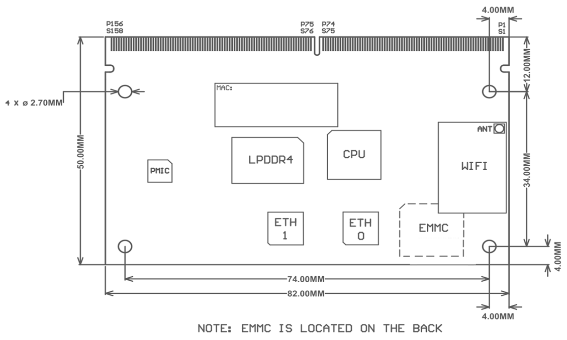
Mechanical Drawings
Module dimensions of the Nitrogen93 SMARC are 82 x 50 mm. Detail drawings are shown below.
Pin Definitions & Functionality (and PIN-MUX, if applicable)
Electrical Characteristics
Absolute Maximum Ratings
The following tables summarizes the absolute maximum ratings for the Nitrogen93 SMARC product series. Absolute maximum ratings are those values beyond which damage to the device can occur. Functional operation under these conditions, or at any other condition beyond those indicated in the operational sections of this document, is not recommended.
Note: Maximum rating for signals follows the supply domain of the signals.
Absolute maximum ratings
| Symbol (Domain) | Parameter | Min. | Max | Unit |
|---|---|---|---|---|
| VSYS_5V | Input voltage for the SOM | -0.5 | +6.0 | V |
| I/O Input/output voltage range | Any I/O pin referred to VDD_1V8; VDDA_1V8; WI-FI_1V8; NVCC_SNVS_1V8 | -0.3 | +2.1 | V |
| I/O Input/output voltage range | Any I/O pin referred to VDD_3V3; VSD_3V3; NVCC_SD2 | -0.3 | +3.6 | V |
| TSTORAGE | Storage Temperature Range | -40 | +125 | °C |
| ANT0; ANT1 | Maximum RF input (reference to 50-Ω input) | NA | +10 | dBm |
| ESD | Electrostatic discharge tolerance | -2000 | +2000 | V |
Recommended Operating Conditions
The following tables summarizes the recommended operating conditions for the Nitrogen93 SMARC product series.
Recommended Operating Conditions
| Symbol (Domain) | Parameter | Min | Typ | Max | Unit |
|---|---|---|---|---|---|
| VSYS_5V | Input voltage for the SOM | 3.3 | 5.0 | 5.5 | V |
| I/O Input/output voltage range | Any I/O pin referred to VDD_1V8; VDDA_1V8; WI-FI_1V8; NVCC_SNVS_1V8 | 1.71 | 1.8 | 1.89 | V |
| I/O Input/output voltage range | Any I/O pin referred to VDD_3V3; VSD_3V3; NVCC_SD2 | 3.0 | 3.3 | 3.6 | V |
| T-ambient | Operating Ambient temperature | -40 | 25 | 85 | °C |
Note: The operating ambient temperature ratings are highly dependent on the design-case, such as the enclosure design, system design, processor activity, GPU/VPU activity, and peripherals used.
Running over 70° C ambient temperature typically requires the implementation of thermal management strategies such as passive (heatsink/spreader). Please contact Ezurio if you need information and guidance for thermal management.
DC Electrical Characteristics / Current Consumption
Several power saving modes are available and are listed in the following table.
Note: These figures are estimates and subject to change.
Typical current consumption
| Mode | Description | Current (Avg) |
|---|---|---|
| Power Saving mode | CPU is on, Stay on Wi-Fi connection only. | 431mA |
| RAM suspend mode | CPU is on, memory and wireless connection are off. | 7.7mA |
| Linux graceful power down mode | All circuits are off. Only the NVCC_SNVS_1V8 PMU is alive and ONOFF pin is accessible to allow turn on of the SOM. | 154uA |
Power Management & Consumption
DC Power Tree
The Nitrogen93 SMARC requires a primary 5V power supply (VSYS) input. This supply is the main power domain to the on-module NXP PCA9451A power management IC (PMIC), which generates all required supply voltages for the module components.
Power Modes
NXP PCA9451A has eight power modes: OFF, READY, SNVS, RUN, STANDBY, PWRDN, PWRUP and FAULT_SD. Below figure shows the state transition diagram showing the conditions to enter and exit each state.
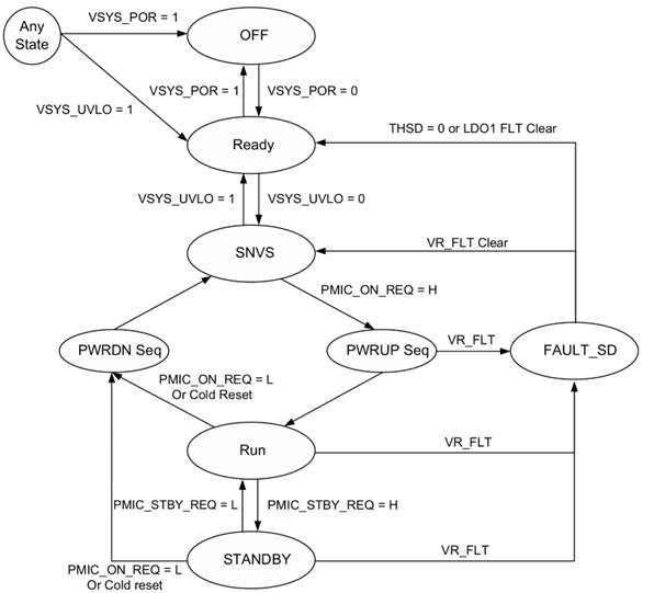
- OFF mode:
PMIC will enter OFF mode from any state when the main power source VSYS_5V falls below Vsys_POR threshold (2.2 to 2.6V; typ.=2.4V). All regulators are OFF and all registers are reset in this mode. - READY Mode:
PMIC enters READY mode when VSYSY_5V is higher than Vsys_POR. The internal LDO VINT is enabled and loads the MTP data to registers. Once the MTP data loading is complete, the state machine is ready to transition to SNVS mode. - SNVS Mode:
PMIC will enter SNVS (Secure Non-Volatile Storage mode) when VSYS_5V exceeds the Vsys_UVLO threshold. LDO1 is powered up and the 32.778KHz buffer starts running. RTC_RESET_B is pulled high after both LDO1 and LDO2 voltage come up.
Note: PMIC_ON_REQ input is masked until RTC_RESET_B is released. PMIC will start power up sequence if PMIC_ON_REQ is asserted high in this mode. - PWRUP Mode:
After RTC_RESET_B is released in SNVS mode, the PMIC starts power up with a pre-defined sequence with PMIC_ON_REQ asserted high.
During PWRUP mode, PMIC_STBY_REQ signal is masked until POR_B is released. The PWRUP mode ends up releasing POR_B and the PMIC is transitioned to RUN mode. - PWRDN Mode:
When PMIC_ON_REQ is low in RUN or STANDBY mode, PMIC enters PWRDN mode, where it starts with pulling down POR_B. and then by turning off each power rail before transitioning to SNVS mode. - RUN Mode:
PMIC operates in RUN mode when PMIC_ON_REQ is driven high and PMIC_STBY_REQ is driven low. When PMIC_STBY_REQ is asserted high in this mode, it is transitioned to STANDBY mode. PMIC_ON_REQ is asserted low, it moves to PWRDN mode. - STANDBY Mode:
PMIC is transitioned to STANDBY mode from RUN mode when both PMIC_ON_REQ and PMIC_STBY_REQ are driven low. If PMIC_ON_REQ is asserted low, then it is transitioned to PWRDN mode. If PMIC_STBY_REQ is driven low, it is transitioned to RUN mode.
| Power Mode | VSYS_5V | PMIC_ON_REQ | PMIC_STBY_REQ |
|---|---|---|---|
| OFF | VSYS_5V<VSYS_POR | x | x |
| READY | VSYS_5V>VSYS_POR | x | x |
| SNVS | VSYS_5V>VSYS_UVLO | LOW | x |
| STANDBY | VSYS_5V>VSYS_UVLO | HIGH | HIGH |
| RUN | VSYS_5V>VSYS_UVLO | HIGH | LOW |
FAULT_SD Mode:
PCA9451A has three kinds of Fault sources.- Thermal shutdown: Transition to SNVS mode or READY mode after Fault_SD mode.
When junction temperature reaches 150℃, it enters FAULT_SD mode after 120μs where regulators are tuned off simultaneously. It stays at FAULT_SD mode until the junction temperature fall below 150℃, then move to READY state if any of LDO1 and LDO2 is fault is triggered. And it will move to SNVS mode if either LDO1 or LDO2 fault is triggered. - Voltage regulator fault during power up: Transition to READY mode after FAULT_SD mode.
Any POK of voltage regulator doesn’t come up within 10ms after regulator is enabled during power up sequence, it stops power-up sequence and then moves into FAULT_SD mode where all regulators are turned off. - Voltage regulator fault in STBY and RUN MODE: Move to FAULT_SD mode in 100ms after fault is detected. Transition to SNVS mode or READY mode after FAULT_SD mode.
- Thermal shutdown: Transition to SNVS mode or READY mode after Fault_SD mode.
Environmental and Reliability
Environmental Requirements
Required Storage Conditions
Prior to Opening the Dry Packing:
The following are required storage conditions prior to opening the dry packing:- Normal temperature: 5~40℃
- Normal humidity: 80% (Relative humidity) or less
- Storage period: One year or less
Regulatory, Qualification & Certifications
Regulatory Approvals
Radio certifications for SOMs with wireless options are held under the specific wireless module listings:
| Order Model with Wireless | Module Product Page | RIG |
|---|---|---|
| N93_SMARC_SOM_1r16e_IF573_3M | Sona IF573 | Sona IF573 Regulatory information |
| N93_SMARC_SOM_1r16e_IF573_3M_i | Sona IF573 | Sona IF573 Regulatory information |
| N93_SMARC_SOM_2r16e_IF573_3M | Sona IF573 | Sona IF573 Regulatory information |
| N93_SMARC_SOM_2r16e_IF573_3M_i | Sona IF573 | Sona IF573 Regulatory information |
Ordering Information
| Order Model | Description |
|---|---|
| N93_SMARC_SOM_1r16e | Nitrogen93 SMARC SOM: i.MX 93 Dual / 1GB / 16GB eMMC / 0 to +70°C |
| N93_SMARC_SOM_2r16e | Nitrogen93 SMARC SOM: i.MX 93 Dual / 2GB / 16GB eMMC / 0 to +70°C |
| N93_SMARC_SOM_1r16e_i | Nitrogen93 SMARC SOM: i.MX 93 Dual / 1GB / 16GB eMMC / -40 to +85°C |
| N93_SMARC_SOM_2r16e_i | Nitrogen93 SMARC SOM: i.MX 93 Dual / 2GB / 16GB eMMC / -40 to +85°C |
| N93_SMARC_SOM_1r16e_IF573_3M | Nitrogen93 SMARC SOM: i.MX 93 Dual / 1GB / 16GB eMMC / IF573 / 0 to +70°C |
| N93_SMARC_SOM_1r16e_IF573_3M_i | Nitrogen93 SMARC SOM: i.MX 93 Dual / 1GB / 16GB eMMC / IF573 / -40 to +85°C |
| N93_SMARC_SOM_2r16e_IF573_3M | Nitrogen93 SMARC SOM: i.MX 93 Dual / 2GB / 16GB eMMC / IF573 / 0 to +70°C |
| N93_SMARC_SOM_2r16e_IF573_3M_i | Nitrogen93 SMARC SOM: i.MX 93 Dual / 2GB / 16GB eMMC / IF573 / -40 to +85°C |
| SMARC_CAR | Kit - Universal SMARC Carrier Board. Includes 3x EFB2471A3S-10MH4L and 2x 001-0021 antennas, power supply, DB9 cable |
| SMARC_CAR_BRD | Universal Carrier Board - SMARC (Note - SOM sold separately) |
Legacy - Revision History
| Version | Date | Notes | Contributors | Approver |
|---|---|---|---|---|
| 0.1 | 5 July 2023 | Preliminary Release | Gary Bisson | Dan Kephart |
| 1.0 | 22 January 2024 | Update muxing tables to match schematics REV10 in Table 8. | Jody Van | Gary Bisson |
| 1.1 | 16 Apr 2024 | Updated to Ezurio branding. Corrected wireless module to IF573. | Dave Drogowski | Jonathan Kaye |
| 1.2 | 19 Apr 2024 | Added an Errata Section | Jody Van | Jonathan Kaye |
| 1.3 | 13 June 2024 | Added SMARC_CAR to orderable parts. | Dave Drogowski | Jonathan Kaye |
| 1.4 | 14 June 2024 | Corrected pins P110 and P111 in Module pin out and Pinmux table | Gary Bisson | Dave Drogowski |
| 1.5 | 17 Sep 2024 | Removed references to JTAG. | Dave Drogowski | Jody Van |
| 1.6 | 2 Jan 2025 | Updated voltage ranges to match SMARC standard. | Eric Graves | Dave Drogowski |
Additional Information
Please contact your local sales representative or our support team for further assistance:
| Headquarters | Ezurio 50 S. Main St. Suite 1100 Akron, OH 44308 USA |
| Website | http://www.ezurio.com/ |
| Technical Support | http://www.ezurio.com/resources/support |
| Sales Contact | http://www.ezurio.com/contact |
Note: Information contained in this document is subject to change.
Ezurio’s products are subject to standard Terms & Conditions.
| © Copyright 2025 Ezurio. All Rights Reserved. Patent pending. Any information furnished by Ezurio and its agents is believed to be accurate and reliable. All specifications are subject to change without notice. Responsibility for the use and application of Ezurio materials or products rests with the end user since Ezurio and its agents cannot be aware of all potential uses. Ezurio makes no warranties as to non-infringement nor as to the fitness, merchantability, or sustainability of any Ezurio materials or products for any specific or general uses. Ezurio or any of its affiliates or agents shall not be liable for incidental or consequential damages of any kind. All Ezurio products are sold pursuant to the Ezurio Terms and Conditions of Sale in effect from time to time, a copy of which will be furnished upon request. Nothing herein provides a license under any Ezurio or any third-party intellectual property right. |